
- Catalogs
- CHANKO SENSOR
- CHANKO CME Series Laser LiDAR Sensor


- Company
- Products
- Catalogs
- News & Trends
- Exhibitions
CHANKO CME Series Laser LiDAR Sensor
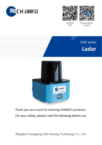
CHANKO CME Series Laser LiDAR Sensor
Before purchasing or using the CME Series Lidar, it is crucial to read the manual thoroughly to select the appropriate model and avoid potential damage or warranty violations. Ensure that users have access to this manual.
Acquisition Channels
The latest manual version can be obtained from the official website, via QR code, or by contacting the sales or technical support teams.
Technical Support
For unresolved issues, contact technical support via email or phone.
Technical Parameters
- Function: Utilizes the Time-of-Flight (TOF) method.
- Detection Distance: 0.05–6 m at 10% reflection rate; 0.05–10 m at 90% reflection rate.
- Illuminant: Infrared laser (905 nm).
- Accuracy: ±20mm; Repeatability: ±10mm.
- Response Time: 40ms; Laser Grade: 1 Class (EN 60825-1).
- Measurement Angle: 270°; Guard Space: 6m.
- Angular Resolution: 0.5°; Scan Frequency: 25Hz.
- Input/Output: Multiple NPN & PNP inputs and outputs available.
- Working Voltage: 10–30VDC; Power Dissipation: <3W.
Environmental Parameters
- Operating Temperature: -20 to 55°C (no frost or condensation).
- Storage Temperature: -30 to 60°C.
- Protection Rating: IP65.
- EMC Standards: EN 61000-6-2:2005 / EN 61000-6-4 (2007-01).
Mechanical Dimensions
Includes diagrams for external dimensions and installation schematics for various mounting brackets.
Electrical Connection
Details on power, output/input interfaces, and Ethernet connections are provided, including signal definitions and functional descriptions.
Area Selection
Instructions for selecting detection regions using input signals.
Interface and Graphics
Spot size characteristics and interface details are provided.
Operation
- Main Applications: Robot environment recognition, building intrusion protection, automatic door behavior recognition, and AGVs.
- Product Overview: Safety protection and area detection functions, configurable via USB or Ethernet.
- Configuration Details: Communication parameters for serial and Ethernet models.
- Host Computer Instructions: Steps for establishing connections, plotting graphics, uploading and downloading data, and switching regions.
Matters Needing Attention
Installation should avoid humid or dirty environments and interference from external light sources. Proper installation methods are recommended to prevent sensor interference.
Environment Considerations for Debugging
Operations should be performed by authorized personnel only, ensuring safety and absence of obstructions.
Maintenance
Regular cleaning of the lens cover is essential to prevent measurement errors. Motor and power failures should be addressed by the manufacturer.
Product Description
Includes procurement information and demonstration of product types.
Fittings of a Machine
Optional accessories such as data cables and anti-collision mounts are available.
Contact Information
Contact details for Shanghai Changjiang Jizhi Sensing Technology Co., Ltd. are provided, including address, website, and phone numbers.
Catalog excerpts
Facebook Page WeChat Official Account Thank you very much for choosing CHANKO's products. For your safety, please read the following before use Shanghai Changjiang Jizhi Sensing Technology Co., Ltd.
Open the catalog to page 1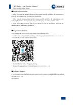
CME Series Lidar Product Manual CME Series LIDAR Product Manual • Before purchasing the product, please read this manual carefully and follow the instructions to select the appropriate model to avoid errors in selection. • Before using the product, please read this manual carefully and follow all instructions to avoid damaging the product, causing property loss, personal injury, or violating warranty terms. • If you include this product as part of your offering, be sure to provide this manual to the intended users or indicate how to obtain it. You can obtain the latest version of the manual in...
Open the catalog to page 2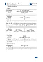
CME Series Lidar Product Manual CME Series LIDAR Product Manual
Open the catalog to page 3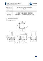
C M E S e r i e s L i d a r P r o d u c t Ma n u a l CME Series LIDAR Product Manual Storage temperature Reidantb anben lie -30~60℃ 80000Lux I P 65 EN 61000-6-2:2005 / EN 61000-6-4 (2007-01) EN 61000-6-1:2005 / EN 61000-6-3 (2007-01) Doublea mplitude: I mm,10-55 Hz; duration per axis: 2 hours Fgure l: ExtemalDi mar si o ns of te CME Lidar
Open the catalog to page 4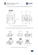
CME Series Lidar Product Manual 2.2 External Dimensions and Installation Diagram of the Bottom Mounting Bracket (unit: Mm) Figure 2: Schematic Diagram of the CME Lidar Installation at the Bottom 2.3 External Dimensions Diagram and Installation Schematic of the Rear Mounting Bracket (unit: Mm) Figure 3: Schematic Diagram of CME Lidar Installation on the Back
Open the catalog to page 5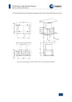
CME Series Lidar Product Manual 2.4 External Dimensions and Installation Diagram of the Collision-Resistant Bracket (unit: Mm) Figure 4 Schematic Diagram of CME LiDAR Collision Avoidance Bracket Installation
Open the catalog to page 6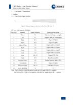
CME Series LIDAR Product Manual I/O Input Line Sequence Definition Note: The NPN input COM IN is positive, while the PNP input COM IN is negative. The NPN output's COM OUT is negative, while the PNP output's COM OUT is positive.
Open the catalog to page 7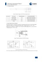
CME Series Lidar Product Manual CME Series LIDAR Product Manual ^CHdNKD 3.1.2 Ethernet Interface Order number 3.2 Input/Output Electrical Diagram NPN input: COM_IN is connected to ground; IN is the input terminal (low level on the optocoupler indicates ON, high level or floating states indicate OFF). Voltage range: DC 12-30 V, 5 mA. PNP Input: Set COM_IN to negative; IN is the input terminal (high level on, low level off). Voltage range: DC 12-30 V, 5 mA.
Open the catalog to page 8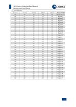
^CHdNKD CME Series Lidar Product Manual CME Series LIDAR Product Manual
Open the catalog to page 9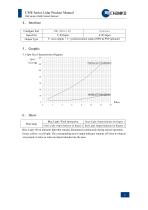
CME Series Lidar Product Manual CME Series LIDAR Product Manual 6> Show Pilot lamp Blue Light: Work indicator light that remains illuminated continuously during normal operation. Green, yellow, or red light: The corresponding area's output indicator remains off when no objects are present; it turns on when an object intrudes into the area.
Open the catalog to page 10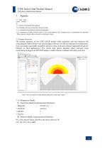
CME Series Lidar Product Manual CME Series LIDAR Product Manual ^CHdNKD 7> Operate 7.1 Main Application Scenarios: (1) Robot Environment Recognition (2) Building Intrusion Protection (Security Field) (3) Automatic Door/Behavior Pattern Recognition (4) Autonomous Guided Vehicles (AGVs) can avoid obstacles; the scanning area is customizable and provides three response options (alarm, slowdown, emergency stop). The primary functions of the CME LiDAR include safety protection and area detection. By connecting the CME LiDAR to the Area Designer software via USB (or Ethernet) for configuration, users...
Open the catalog to page 11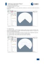
CME Series Lidar Product Manual 7.4 Instructions for Using the Host Computer 7.4.1 Establish connection As shown below, connect the serial-port model radar by clicking Icon 1, and connect the Ethernet model radar by clicking Icon 2. 7.4.2 graphic plotting (1)As shown in Figure 1, click the number of obstacle avoidance groups to be drawn in the left list. The serial port type supports drawing 1–31 groups, while the Ethernet type supports drawing 1–15 groups; the "0 " area is set as the default unprotected zone. (2)As shown in Figure 2, select the obstacle avoidance area; the three zones are independent...
Open the catalog to page 12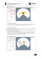
CME Series Lidar Product Manual 7.4.3 Upload Measurement Data (1)As shown in Figure 1, click "Upload Original Data" to obtain the environmental map around the obstacle avoidance radar. (2)As shown in Figure 2, you can view the current protection status of the three zones and select a region. 7.4.4 Download drawing data (1)As shown in Figure 1, click the download icon to upload your drawing data to the obstacle avoidance radar and wait for the "Data Transfer Complete" prompt. (2)Data transfer is complete. The obstacle avoidance radar will restart to load the obstacle avoidance data, and a new...
Open the catalog to page 13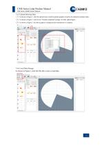
CHeINKD 7.4.5 Upload Drawing Data (1) As shown in Figure 1, click the upload icon to load the plotted graphics stored in the obstacle avoidance radar. (2) As shown in Figure 2, wait for the "Transfer completed" prompt. If it fails, upload again. (3) As shown in Figure 3, the drawn graphic is displayed after transmission is complete. ik£ l-.ttfilfrfiW <2*/32) il-:/h I . ft KiWrSlK (25/32) iFYV: I', ft Stfr&m <26/32) £& l.ftS!fc'rEt«((27/32) it it LftSMf&«<28/32} iKAi |-.ft)Sfe&tK<2S/32) ili/h I'.ftKlMr&lH <30/32) lEVfe l.ft KitfrftlK <ai/32) iE^lft-e«rfe«(32/32) ftttjrdtt 7.4.6 Local Data StorageAs...
Open the catalog to page 14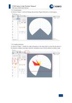
CME Series Lidar Product Manual CME Series LIDAR Product Manual ^CHdNKD 7.4.7 Switch Region As shown in Figure 1, click the Settings tab and select Region Selection to switch regions. As shown in Figure 1, modify the angle information in the input field to correct the deviation in the obstacle avoidance area angle caused by installation issues with the obstacle avoidance radar.
Open the catalog to page 15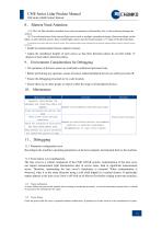
CME Series Lidar Product Manual CME Series LIDAR Product Manual ^CHSNKD 8> Matters Need Attention ((1)) The CME lidar should be installed away from environments with humidity, dirt, or those that may damage the sensors. (2) To avoid interference from external light sources such as sunlight, incandescent lamps, fluorescent lamps, strobe lights, or other infrared sources, these external light sources must be located outside a ±5° range of the detection plane. (3) Interference from similar light sources should be avoided. When installing multiple sensors simultaneously, the following installation...
Open the catalog to page 16All CHANKO SENSOR catalogs and technical brochures
 Chanko proximity switch catalog
23 Pages
 CHANKO-INTRODUCTION(2023)
42 Pages
 CA20 series
5 Pages
 CX2 series
4 Pages
 CX6-DN10
13 Pages
 CPK series
6 Pages
 CPG-TF25 series
6 Pages
 CPA series
6 Pages
 CL17 Series
8 Pages
 CL30 Series
11 Pages
 CL18 Series
11 Pages
 CL12 Series
11 Pages
 CL08 Series
11 Pages

- Proximity switch
- Cylindrical proximity sensor
- Inductive proximity sensor
- Photoelectric sensor
- IP67 proximity sensor
- Industrial cable
- Optical cable
- PVC-sheathed cable
- Displacement transducer
- DC proximity sensor
- Optical data cable
- Linear displacement sensor
- Rectangular photoelectric sensor
- Light barrier
- Single-conductor cable
- Plastic proximity sensor
- Multibeam light curtain
- Threaded proximity sensor
- Analog displacement transducer
- M12 proximity sensor