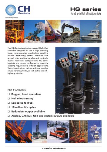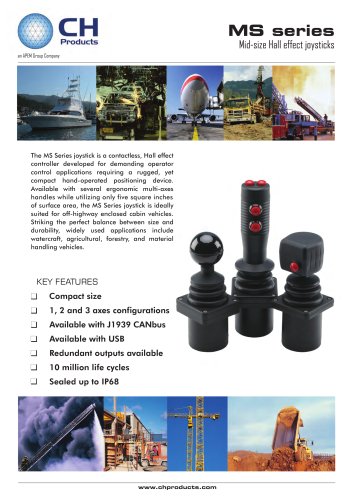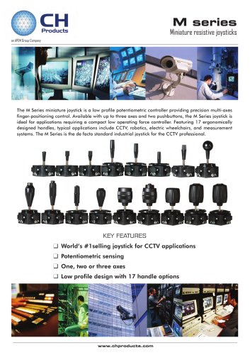
Catalog excerpts
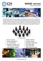
9000 series Inductive sensing joysticks an APEM Group Company The 9000 Series is ideal for those applications that demand proportional control with a low profile below the panel. Developed from the proven 7000 Series, the 9000 Series employs the same, highly proven, contactless, inductive sensing and circuitry. This joystick offers self-centering, omni-directional functionality, and utilizes the exclusive ‘locking cam’ system to rigidly secure the highly repeatable mechanism around the precision groundsteel operating shaft. High precision air wound coils are mounted directly onto the SMT circuitry, delivering enviable accuracy while further minimizing the installed depth of the joystick. KEY FEATURES One or two axes Signal mixing options 5 - 15V operation Optional “at center” and “internal fault” detection Dual redundant outputs. Infinite resolution Inductive sensing Consistent performance IP65 above panel Long service life Wide range of handles
Open the catalog to page 1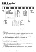
9000 series Inductive sensing joysticks OPTION SELECTION Single Axis Dual Decode/Dual Outputs Dual Decode/Separate Fault & Center Detect Dual Decode/Fault Detect Dual Decode/Combined Fault & Center Detect 1. Rear Mounting 2. Drop In Mounting Single Decode Dual Decode/Center Detect Pushbutton Tactile AM Fluted with Pushbutton AN Two Pushbuttons AT NOTES 1. BEZEL OPTIONS For drop in mounting, please specify bezel option 6 or 7. For sub-panel mounting, no bezel is necessary, unless the boot is required to seal to the front face of the panel in which case bezel option 4 should be specified....
Open the catalog to page 2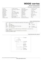
9000 series Inductive sensing joysticks TECHNICAL SPECIFICATIONS Life C ycles Supply Voltage O utput Signal T olerance Preferred Load Stainless Steel Brass, Acetal, N ylon Acetal & H ardened Steel OpO perating Lever D eflectionO peratin+/-g Lever D eflection : +/-18° Operating Lever Deflection CABLE SPECIFICATIONS 14/0.12 - Fourteen strands of 0.12mm diameter tinned annealed copper wire PVC insulated to a nominal OD of 1mm Red Blue Green Orange : +Vcc : X Axis Wiper : Center Tap Reference : Center Detect, or Combined Fault & Center Detect Black Yellow : Mirror of X Axis Wiper White Grey :...
Open the catalog to page 3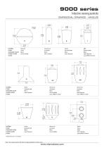
9000 series Inductive sensing joysticks DIMENSIONAL DRAWINGS - HANDLES MATERIAL FINISH STANDARD COLOR OTHER COLORS NOTES: Phenolic Gloss Black Not Available Aluminium Anodised Black Not available Nylon Sparked Matt Black Upon Request ABS Sparked Matt Black Upon Request Uses APEM IS Switch MATERIAL FINISH STANDARD COLOR OTHER COLORS NOTES: Nylon Sparked Matt Black Upon Request Aluminum Anodised Black Not Available Uses APEM IA Switch Aluminium Anodised Black Upon Request Uses APEM IA Switch MATERIAL FINISH STANDARD COLOR OTHER COLORS NOTES: Nylon Sparked Matt Black Upon Request Aluminum...
Open the catalog to page 4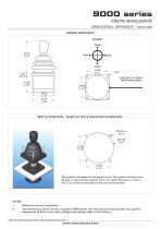
9000 series Inductive sensing joysticks DIMENSIONAL DRAWINGS - continued GENERAL DIMENSIONS POLARITY North 3.20* LEADS EXIT TO THE EAST VIEWED FROM ABOVE DROP IN MOUNTING - PANEL CUT-OUT & MOUNTING INSTALLATION The joystick is dropped into the panel cut-out. The joystick and boot must be kept in place by bezel (option 6 & 7). For panel thickness of <3mm, M3 x 16 countersunk machine screws are recommended. NOTES: 1. Dimensions are in mm/(inch) 2. The dimensions shown are for a generic 9000 Series with the conical E type handle. For specific dimensions of this or any other configuration...
Open the catalog to page 5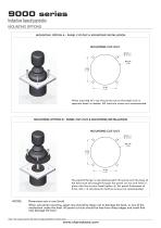
9000 series Inductive based joysticks MOUNTING OPTIONS M OUNTING OPTION A - PANEL CUT-OUT & M OUNTING INSTALLATION When mounted this way the panel acts as the bezel and no separate bezel is needed. M3 machine screws are recommended. MOUNTING OPTION B - PANEL CUT-OUT & MOUNTING INSTALLATION The joystick flange is mounted beneath the panel and the base of the boot must be brought through the panel cut-out and held in place with the circular bezel (option 4). For panel thicknesses of 3mm, M3 x 16 countersunk machine screws are recommended. Dimensions are in mm/(inch) When sub panel mounting,...
Open the catalog to page 6
9000 series Inductive sensing joysticks CONFIGURATION OPTIONS CIRCUITRY The 9000 Series joystick operates by passing an oscillating current through a drive coil, directly mounted at the lower end of the operating lever, and immediately above the four sensing coils. When the shaft and drive coil moves away from the centre, the signals detected in each opposing pair of coils increase nominally in proportion to deflection. The phase of those signals determine the direction. Synchronous electronic switches followed by integrating amplifiers provide DC signals directly equivalent to those of...
Open the catalog to page 7All Ch products catalogs and technical brochures
-
1000 series
6 Pages
-
NZ series
5 Pages
-
SN series
4 Pages
-
HF series
10 Pages
-
4000 series
7 Pages
-
TW Series Data Sheet
4 Pages
-
Single Axis Throttle Data Sheet
15 Pages
-
HG Data Sheet
15 Pages
-
MS Series III
14 Pages
-
IPD Ultima
3 Pages
-
HT - Series II Data Sheet
14 Pages


