Catalog excerpts

Data Sheet English
Open the catalog to page 1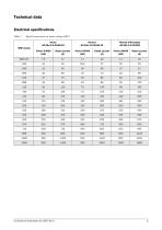
Technical data Electrical specifications Table 1 Typical motor power at mains voltage 400 V Heavy AC-53a 5.0-30:50-10 Normal with bypass AC-53b 3.0-30:300
Open the catalog to page 2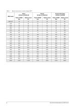
Typical motor power at mains voltage 460 V Heavy AC-53a 5.0-30:50-10 Normal with bypass AC-53b 3.0-30:300
Open the catalog to page 3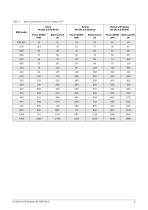
Typical motor power at mains voltage 525 V Heavy AC-53a 5.0-30:50-10 Normal with bypass AC-53b 3.0-30:300
Open the catalog to page 4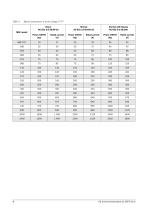
Typical motor power at mains voltage 575 V Heavy AC-53a 5.0-30:50-10 Normal with bypass AC-53b 3.0-30:300
Open the catalog to page 5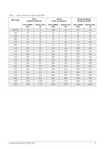
Typical motor power at mains voltage 690 V Normal with bypass AC-53b 3.0-30:300
Open the catalog to page 6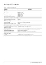
General electrical specifications Table 6 General electrical specifications General Mains supply voltage Control supply voltage Mains and Control supply frequency Number of fully controlled phases Recommended fuse for control supply Control signal inputs Digital input voltage Digital input impedance to GND (0 VDC) Analogue input voltage/current Analogue input impedance to GND (0 VDC) Voltage signal 125 kΩ, current signal 100 Ω Control signal outputs Output relays contact 8 A, 250 VAC or 24 VDC resistive load; 3 A, 250 VAC inductive load (PF 0.4) Analogue output voltage/current Analogue...
Open the catalog to page 7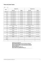
Fuses and power losses NOTE: Short circuit withstand: MSF-017-MSF-060 5000 rms A when used with K5 or RK5 fuses MSF-075 - MSF-14510000 rms A when used with K5 or RK5 fuses MSF-170 - MSF-250 18000 rms A when used with K5 or RK5 fuses
Open the catalog to page 8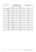
Power losses Power loss at rated motor load [W] No losses with bypass Power consumption control card [VA]
Open the catalog to page 9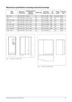
Mechanical specifications including mechanical drawings MSF Model Mounting position [Vertical/ Weight [kg] Horizontal] Cooling system Protection class
Open the catalog to page 10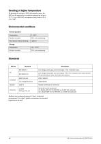
Derating at higher temperature By derating the current to 80% of nominal current, the MSF can be operated at an ambient temperature of up to 50 C. E.g. a MSF-045 can operate a heavy load of 36 A (45 A*0.8). Environmental conditions Normal operation Temperature Relative humidity Max altitude without derating Storage Temperature Relative humidity Standards Market Low voltage switch gear and control gear - Part 1: General rules. Low voltage switch gear and control gear - Part 4-2: Contactors and motor starters AC semiconductor motor controllers and starters Russian certificate of conformity...
Open the catalog to page 11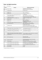
Power- and signal connectors Table 9 Protective Earth Protective Earth Control supply voltage to PCB terminal 11 and 12, 10 k potentiometer, etc. 0-3 V --> 0; 8-27 V--> 1. Max. 37 V for 10 sec. Impedance to 0 VDC: 2.2 k. +12 VDC ±5%. Max. current from +12 VDC: 50 mA. Short circuit-proof but not overloadproof. Impedance to terminal 15 (0 VDC) voltage signal: 125 k, current signal: 100 . 0 VDC 0-3 V --> 0; 8-27 V--> 1. Max. 37 V for 10 sec. Impedance to 0 VDC: 2.2 k. +12 VDC ±5%. Max. current from +12 VDC = 50 mA. Short circuit-proof but not overload-proof. Analogue output contact: 0-10 V,...
Open the catalog to page 12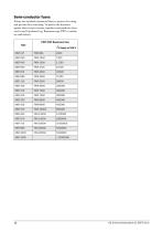
Semi-conductor fuses Always use standard commercial fuses to protect the wiring and prevent short circuiting. To protect the thyristors against short-circuit currents, superfast semiconductor fuses can be used if preferred (e.g. Bussmann type FWP or similar, see table below). FWP/FWJ Bussmann fuse Type
Open the catalog to page 13
CG Drives & Automation Sweden AB
Open the catalog to page 14All CG Drives & Automation (former Emotron) catalogs and technical brochures
-
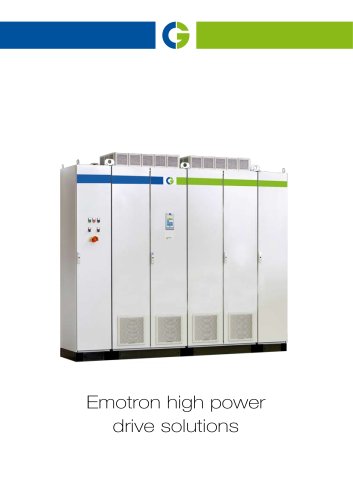
High Power in cabinets
4 Pages
-
Emotron FDU 2.0 AC Drive
16 Pages
-
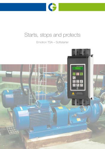
Emotron TSA Softstarter
8 Pages
-
Emotron DCM control unit
8 Pages
-
Emotron EMX-P
2 Pages
-
Emotron EMX-R
2 Pages
-
Emotron EMX-D
2 Pages
-
Emotron MSF 2.0 Softstarter
5 Pages
-
Emotron AFE drives
8 Pages
-
Emotron VFX 2.0 AC drive
9 Pages
-
Technical catalogue AC Drives
36 Pages


