Warrior 32 MU Receiver
1 /3Pages

Warrior 32 MU Receiver
1 /3Pages
Catalog excerpts

Engineering SpecSheet MU Machine Unit Features S Compact Designed to IP65/IP67 Standards S 900MHz Operation S Designed to ICS 8 NEMA Crane Specification S 8 DIP Switches Allow for Configurability The MU Machine Unit is a low cost machine-mounted unit intended for use on industrial systems. The MU is self-contained and prefigured providing a no-touch solution. The unit is available in 900MHz for maximum flexibility. The MU will accept control commands from HH2S and MCB varieties in the product family. The MU can be mounted by utilizing the included mounting feet or a 2-bolt mounting plate. The sturdy enclosure allows the MU to operate worry free in harsh weather conditions. A single pre-wired number-keyed 25-wire-fed cable is integral to the unit that allows easy connection to the controlled devices. 8.327” x 6.358” x 3.937” (211.50mm x 161.50mm x 100mm) NEMA 1,2, 4, 4X IP65/IP67 Four wall mounting brackets and Four M4 x 10mm LG. self-tapping screws Power Operating Voltage 110 to 220VAC @ 50-60Hz 7 to 36VDC 10 to 28VAC @ 50-60Hz Operating Power 0.35A Environment Operating Temp -40°C to 70°C (-40°F to 158°F) Storage Temp -40°C to 80°C (-40°F to 176°F) Humidity 0 - 95% non-condensing Enclosure Dimensions Durability Mounting Indicator (LED) White Used during Association Radio Frequency (MHz) Power License Antenna Safety Circuit Two (Series) Contact Rating Control Relays Sixteen Type Form A MU Machine Unit September 2017
Open the catalog to page 1
ERVIS..MU Machine Unit Engineering SpecSheet 25-Lead Wiring Harness Individual Wire Assignments Wire 16-System Relays Schematic Diagram The sixteen system relays are divided into four groups of four relays each; K1 through K4, K5 through K8, K9 through K12, and K13 through K16. Groups 1 through 3 perform related functions, group 4 contains the MLC Safety Circuit, and each group has a shared independent fused bus. MU Machine Unit September 2017
Open the catalog to page 2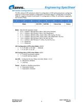
Engineering SpecSheet DIP Switch Configurations The MU utilizes 8 DIP switches to allow for configuration of A/B cycling sequences, configuring relays for 4-wire control systems, configuration of Auxiliary Relay A, configuration of Auxiliary Relay B, mapping of button 9 and button 10, configuration of Relay 16, and button mapping for the Auxiliary Relay. Mode - Sets the MU operation mode: • 0 0 0 = 3-Motion. BR/TR/Hoist 3-Wire. A/B cycling (Default). Aux M/L - Configures the Aux Relay only when Mode = 0 0 X • 0 = Momentary (Default). Assoc. - Enables or disables...
Open the catalog to page 3All Cervis catalogs and technical brochures
 BU-9H16AF
2 Pages
 SmaRT Base Unit BU-2H8D
3 Pages
 PG-xH14 Pistol Grip Remote
2 Pages
 PG-xH12JS Pistol Grip Remote
2 Pages
 HH-218 Handheld Remotes
2 Pages
 BU-xH24XF
2 Pages
 BU-9H18XF
3 Pages
 BU-xH16F
2 Pages
 PG - xH12JS
2 Pages
 BU - x H16R
3 Pages
 SmaRT BU - xH 6R
3 Pages
 LongRT Base
2 Pages
 LongRT Console Box
2 Pages
 MINExpo 2016
1 Page
 TM70 CSA/UL
2 Pages
 TM70 Handheld
2 Pages
 IK4
IK42 Pages
 iK 3
iK 33 Pages
 iK 2
iK 22 Pages
 TM70 Console Box
2 Pages
 SmaRT Connect
2 Pages
 SmaRT BU-X00H
2 Pages
 SmaRT-BU-xH16AF
2 Pages
 SmaRT BU-XH20XF
2 Pages
 SmaRT BU-XH18XF
3 Pages
 SmaRT BU-XH1R
4 Pages
 SmaRT EBU
2 Pages
 SmaRT 18 Button with Display
2 Pages
 SmaRT 18 button
2 Pages
 SmaRT PG-XH12JS
2 Pages
 SmaRT PG-XH14-DIS
2 Pages
 SmaRT PG-XH14
2 Pages
 SmaRT BU-2H8D Series
3 Pages
 SmaRT BU-9H8D
3 Pages
 SmaRT DIN-9H1R5 Base Unit
2 Pages
 SmaRT DIN-9H4R-2DI Base Unit
3 Pages
 SmaRT BU-xH16R
3 Pages
 SmaRT BU-xH6R
3 Pages
 SmaRT Console Box
2 Pages
 SmaRT MCB
2 Pages
 SmaRT 10 Button
1 Page
 SmaRT 2,4,6 Button
2 Pages
 Warrior 42-CB Console Box
2 Pages
 Warrior MU6E Receiver
1 Page
 Warrior 42-MCB
2 Pages
 Warrior 32-MCB
2 Pages
 Material Handling Catalog
14 Pages
 LongRT Base Unit
2 Pages
 SmaRT Wireless Catalog
27 Pages


- Digital I/O
- Analog I/O
- Wireless remote control
- Industrial remote control
- Remote control with buttons
- IP65 remote control
- Radio receiver
- Joystick remote control
- Compact remote control
- Remote control receiver
- Analog input module
- Remote control with toggle switch
- Remote control with integrated display
- Wireless receiver
- IP65 joystick
- 6-button remote control
- 4-button remote control
- Digital input module
- 10-button remote control
- Belt remote control