LongRT Base
1 /2Pages

LongRT Base
1 /2Pages
Catalog excerpts
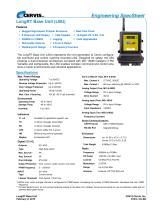
Engineering SpecSheet 0k LongRT Base Unit (LBU) Features S Rugged High-Impact Polymer Enclosure S Real-Time Clock S 8-Character LED Display S CAN Capable S 16-Digital I/O, 2-AO, 2-AI S 450MHz to 470MHz S Logging S Field Upgradeable S Removable Antenna S 2-Form-C Relays S Weatherproof Design S 2-Frequency Counters The LongRT Base Unit (LBU) represents the next generation of Cervis configurable command and control machine-mounted units. Designed for safety, the LBU employs a dual processor architecture compliant with ISO 13849 Category 3 Pld. Versatile and configurable, the LBU enables complex command and control solutions in harsh environments and industrial applications. Outputs Type Max. Source I Avg. Source I One H-Bridge Output Protection PWM Frequency INPUT Type I Sense Threshold Total Weight Radio Frequency RF Power License Modulation Range Antenna Specifications Max. Power Ratings Operating Voltage Reverse Voltage Protection Over Voltage Protection Operating Power Max. Cont. I Sourcing Environment Operating Temp Storage Temp Humidity Available for application specific use Lit when message transmitted Lit when message received Lit when safety-link is active Blinks during normal operation 8-character LED M1-M16 High-Side switch 4A 2A M1 & M2 Over current; under current; over temp. 0 - 1000Hz* M1-M16 Current sense 5mA typical; 10mA max. Form-C RELAY (Two, M17 & M18) Max. Contact V 277VAC, 30VDC Max. Contact I 8A max. switching @ 250VAC or VDC Analog Output (Two, M19 & M20) Voltage Range 0V to Input Voltage Drive Current 30mA Analog Input (Four, M21-M24) Voltage Range 0V to Input Voltage Input Impedance 10000Q Analog Input (Two, M25 & M26) Frequency Counters Serial Communications CAN Protocol SAE J1939/CANopen RS-232 Port Upgrade/Debug 0.680kg (1.5lbs) 450MHz to 470MHz 100mW (+20 dBm max) Certified FCC Part-90 2-GFSK Up to One Mile External, RP-TNC 50Q port *1000Hz max. when a single channel is configured for PWM output. Increasing the number of PWM channels decreases the max. PWM frequency. ** For best performance, do not connect antenna directly to the base unit. Instead, Cervis recommends to use an extension cable with an antenna base plate mount. LongRT Base Unit February 9, 2015
Open the catalog to page 1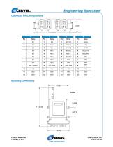
Engineering SpecSheet Mounting Dimensions LongRT Base Unit February 9, 2015
Open the catalog to page 2All Cervis catalogs and technical brochures
 BU-9H16AF
2 Pages
 SmaRT Base Unit BU-2H8D
3 Pages
 PG-xH14 Pistol Grip Remote
2 Pages
 PG-xH12JS Pistol Grip Remote
2 Pages
 HH-218 Handheld Remotes
2 Pages
 BU-xH24XF
2 Pages
 BU-9H18XF
3 Pages
 BU-xH16F
2 Pages
 PG - xH12JS
2 Pages
 BU - x H16R
3 Pages
 SmaRT BU - xH 6R
3 Pages
 LongRT Console Box
2 Pages
 MINExpo 2016
1 Page
 TM70 CSA/UL
2 Pages
 TM70 Handheld
2 Pages
 IK4
IK42 Pages
 iK 3
iK 33 Pages
 iK 2
iK 22 Pages
 TM70 Console Box
2 Pages
 SmaRT Connect
2 Pages
 SmaRT BU-X00H
2 Pages
 SmaRT-BU-xH16AF
2 Pages
 SmaRT BU-XH20XF
2 Pages
 SmaRT BU-XH18XF
3 Pages
 SmaRT BU-XH1R
4 Pages
 SmaRT EBU
2 Pages
 SmaRT 18 Button with Display
2 Pages
 SmaRT 18 button
2 Pages
 SmaRT PG-XH12JS
2 Pages
 SmaRT PG-XH14-DIS
2 Pages
 SmaRT PG-XH14
2 Pages
 SmaRT BU-2H8D Series
3 Pages
 SmaRT BU-9H8D
3 Pages
 SmaRT DIN-9H1R5 Base Unit
2 Pages
 SmaRT DIN-9H4R-2DI Base Unit
3 Pages
 SmaRT BU-xH16R
3 Pages
 SmaRT BU-xH6R
3 Pages
 SmaRT Console Box
2 Pages
 SmaRT MCB
2 Pages
 SmaRT 10 Button
1 Page
 SmaRT 2,4,6 Button
2 Pages
 Warrior 42-CB Console Box
2 Pages
 Warrior MU6E Receiver
1 Page
 Warrior 42-MCB
2 Pages
 Warrior 32-MCB
2 Pages
 Warrior 32 MU Receiver
3 Pages
 Material Handling Catalog
14 Pages
 LongRT Base Unit
2 Pages
 SmaRT Wireless Catalog
27 Pages


- LIMING analog I/O
- LIMING wireless remote control
- LIMING industrial remote control
- LIMING remote control with buttons
- IP65 remote control
- LIMING radio receiver
- Joystick remote control
- LIMING compact remote control
- LIMING remote control receiver
- Analog input module
- Remote control with toggle switch
- LIMING remote control with integrated display
- Wireless receiver
- IP65 joystick
- 6-button remote control
- 4-button remote control
- Digital input module
- 10-button remote control
- Belt remote control