Monolithic Multilayer Actuators
1 /16Pages

Monolithic Multilayer Actuators
1 /16Pages
Catalog excerpts

Multifunctional Ceramics Division CeramTec GmbH Multifunctional Ceramics Division Luitpoldstraße 15 91207 Lauf Germany MF070006 • EN • 1.000 • 1011 • echolot (3907) • Printed in Germany Monolithic Multilayer Actuators Operation and Applications
Open the catalog to page 1
Monolithic Multilayer Actuators This brochure is a supplement to CeramTec´s ”Piezoelectric Components“ publication, where a • High actuating forces number of terms and correlations are described in • Extremely short response times detail. Abbreviations and symbols are explained in • Fine tunable actuating stroke The function of monolithic multilayer actuators the glossary below. is based on the piezoelectric effect. A piezoceramic material expands in the direction of the electrical eld when a voltage is applied to it. The required eld strength to achieve a deformation of 1.5 to 1.7 % is approx....
Open the catalog to page 2
3 In practical use, piezoelectric actuators exhibit a Active surfaces number of properties which distinguish them from When an actuator is in operation, a high eld other electronic components. These properties should be carefully taken into account and appro- priate engineering support should be provided Since the actuator is expected to elongate (i.e., throughout application, development and imple- expand longitudinally), its insulating coating is very mentation phases. thin. This coating is sufcient to prevent electrical breakdown, however it does not protect against Labor safety Electrically...
Open the catalog to page 3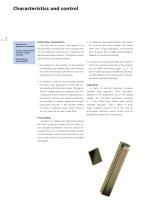
4 Deformation characteristics • Actuators are sensitive to scratching • A mechanical pre-stressing device must prevent • Surface contamination must be avoided carefully • Pre-stressing is recommended The fact that an actuator will expand in an the actuator from being loaded with tensile electrical eld is primarily due to the resulting rota- stress. Even in static applications, a pre-stressing tion and alignment of domains (i.e., crystal areas of force of approx. 0.5 FB is highly recommended to identical polarization direction). This behavior-causes stabilize the mechanical assembly. non-linearities...
Open the catalog to page 4
Driving equipment Domain movements within the electrical eld The displacement (s) of an actuator follows the are associated with mechanical and electrical los- received charge (Q) with good linearity. Therefore ses. Actuators will become hot in operation. The the current (I = dQ/dt) is equivalent to the velocity power dissipation rate may reach 30 % of the input of the actuator endplates (v = ds/dt). The steepness power level. (slewrate) of uctuations in the current (dI/dt) is • Actuators produce heat then equivalent to the acceleration of the actuator An actuator‘s surface temperature must not...
Open the catalog to page 5
Precision mechanics: The product life of an actuator is highly depen- • Servo drives dent upon the individual application. CeramTec’s • Stepper motors endurance tests are performed under the following • Positioning tables • Chart recorder drives Control signal: • Pneumatic and hydraulic valves Rise time: • Vibration damping Holding time: • Engraving heads for intaglio printing Fall time: • Proportioning valves Surface temp.: Mechanical engineering: Optics: • CCD camera systems Under these conditions, the product life of • Optical waveguide splicers CeramTec actuators exceed 109 cycles. The longest...
Open the catalog to page 6
7 Maximum displacement versus voltage Displacement versus voltage actuator size 10*10 mm 2, 28 mm active length 1000 actuator size 7*7 mm 2, 28 mm active length actuator size 7*7mm 2, 28mm active length actuator size 7*7mm 2, 28mm active length Prestressing force/N Operation chart Displacement/µm; Loss energy/mJ Displacement, loss energy and capacitance versus prestessing force Actuator force versus voltage
Open the catalog to page 7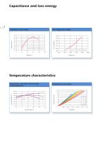
Capacitance and loss energy 8 Capacitance versus voltage Loss energy versus voltage Loss energy/mJ actuator size 7*7mm 2, 28mm active length actuator size 7*7mm 2, 28mm active length Temperature characteristics Displacement, capacitance and loss energy versus temperature Displacement versus charge
Open the catalog to page 8
Product life Leakage current versus time actuator size 7*7mm 2, 28mm active length 2,00 Operation cycles Energy balance (assuming f = FB / 2) Actuator 7 x 7 x 40 UB = 200 V FB = 2200 N Wel = ½ CUB2 Coupling coefcient: Power efciency:
Open the catalog to page 9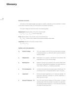
10 Parameter conversion The charts on the foregoing pages each apply to a specic component, but the parameter of interest can be easily converted to allow for the dimensions of the desired component. For a given voltage and mechanical strain, the following applies: Displacement: depends solely on the active actuator length. Lactive = Ltotal – Lpassive (Lpassive = 2 mm in most cases) Force: depends solely on the actuator‘s active cross-sectional area. Aactive = Atotal – 0.6 mm x b (b = width of the actuator according to data sheet) Capacitance: depends on the active actuator volume. Vactive =...
Open the catalog to page 10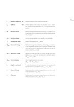
Resonant frequency Hz Resonant frequency of the mechanical assembly. c33 Stiffness N/m Inherent rigidity of the actuator. In calculating actuator proper- ties, the field strength dependence of c33 must be duly taken into Electrical energy absorbed by the actuator as it is charged. It can be calculated from the capacitance and ultimate charging voltage Electrical energy supplied by the actuator during discharge T| . Electrical loss factor Mechanical energy delivered by the actuator. W , is a function of the mechanical actuator load. It reaches its maximum value when the force at the operating...
Open the catalog to page 11
Monolithic Multilayer Actuators This brochure is a supplement to CeramTec´s ”Piezoelectric Components“ publication, where a • High actuating forces number of terms and correlations are described in • Extremely short response times detail. Abbreviations and symbols are explained in • Fine tunable actuating stroke The function of monolithic multilayer actuators the glossary below. is based on the piezoelectric effect. A piezoceramic material expands in the direction of the electrical eld when a voltage is applied to it. The required eld strength to achieve a deformation of 1.5 to 1.7 % is approx....
Open the catalog to page 15All CERAMTEC catalogs and technical brochures
 TOOLS FOR TURNING
188 Pages
 SYSTEM S3
56 Pages
 RAG
RAG37 Pages
 HARD TURNING
60 Pages
 CERAMIC INSERTS
96 Pages
 PERLUCOR® Transparent Ceramics
16 Pages
 Lasering of Ceramics
6 Pages


Archived catalogs
 Ceramic Materials
4 Pages
 SPK® PFK90-TN
132 Pages
 SPK Tools for hard materials
112 Pages
 CeramCool® Substrates
2 Pages
 Tools for Turning
188 Pages
 PcBn for cast iron Machining
24 Pages
 triduon thermo tames Temperature
16 Pages
 ALUTIT Aluminum Titanate
6 Pages
 ALOTEC
11 Pages
 New Milling Cutter Generation
36 Pages
 Materials for gas ignition
2 Pages
 SPK Tools for turning
340 Pages
 SPK Milling Tools
76 Pages


- Milling tool
- Solid milling cutter
- Milling tool with replaceable insert
- Steel milling cutter
- Clamping milling cutter
- Grade
- Face milling cutter
- Shell-end milling cutter
- Cutting milling cutter
- High-performance milling cutter
- Shoulder milling cutter
- Roughing milling cutter
- Turning grade
- Steel grade
- High-precision milling cutter
- Carbide grade
- CBN grade
- Milling cutter with negative insert
- Milling grade
- Cast iron grade