CL
1 /16Pages

CL
1 /16Pages
Catalog excerpts

POWER TRANSMISSION LEADING BY INNOVATION
Open the catalog to page 1
CONTENTS Page Explanation of the Technical Data and selection procedure of CENTALINK 5 -8 Combination of CENTALINK with CENTAX couplings 14 CENTA products for similar applications 15 Worldwide service network 16 Erlauterung der technischen Daten und Auslegung von CENTALINK 5 - 8 CENTA Kupplungen fur ahnliche Einsatzgebiete 15 Weltweites Vertriebsnetz 16 This catalogue shows the extent of our CENTALINK-shaft range at the time of printing. This program is still being extended with further sizes and series. If you are unable to find a suitable shaft for your application please...
Open the catalog to page 2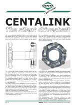
The silent driveshaft The internationally patented CENTALINK shafts are on the market since 1991, more than 10,000 units perform well in severe applications. Many of them have reached more than 50.000 hrs in service without any problems. Die international patentierten CENTALINK-Gelenkwellen sind seit 1991 auf dem Markt, mehr als 10.000 Einheiten haben sich in harten Einsätzen bestens bewährt. Viele davon haben Laufzeiten von mehr als 50.000 Stunden ohne Probleme erreicht. The CENTALINK shaft consists of links which are designed for efficiency using flexible bushes for push and pull. In each link...
Open the catalog to page 3
CE CENTALINK joints offer the following outstanding advantages: Die CENTALINK Gelenkwellen bieten folgende hervorragende Eigenschaften: • compensation for considerable axial, radial and angular misalignment • Ausgleich von großen axialen, radialen und winkeligen Verlagerungen • with very low reacting forces and linear characteristics • Dabei geringe Rückstellkräfte, mit linearer Kennlinie, d.h. proportional zur Auslenkung und fast nicht beeinflußt vom übertragenen Drehmoment • constant velocity transmission, angular deflection of the two joints may be different • silent operation, transmitted...
Open the catalog to page 4
CE Explanation of technical data and selection of CENTALINK Erläuterung der technischen Daten und Auslegung von CENTALINK Nominal torque First the CENTALINK shaft selection has to be based on the nominal torque TKN. This is allowable continuously within the permitted speed range. Under difficult operation conditions additional service factors may be required. For high ambient temperature the temperature factor of St1 has to be considered. Nenndrehmoment Die Auslegung der CENTALINK Gelenkwellen muß zunächst nach dem Nenndrehmoment TKN erfolgen. Dieses ist im zulässigen Drehzahlbereich dauernd...
Open the catalog to page 5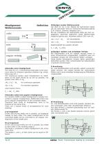
Zulässiger axialer Wellenversatz Der Wert für ∆Ka in der Tabelle der technischen Daten gilt als maximaler Wert für transiente Betriebszustände (z.B. Schock, schwerer Seegang usw.). Bei der Installation der Gelenkwelle sollte der fest vorgegebene, dauernde (statische) axiale Wellenversatz möglichst gering sein, höchstens jedoch 20% vom ∆Ka. ∆Wa ≤ 0,2 · ∆Ka Reaktionskraft bei axialem Versatz: Fa = ∆Wa · Ca (KN) Zulässiger radialer und winkeliger Versatz Bei Gelenkwellen wird ein radialer Versatz immer in einen Winkelversatz umgewandelt. Zusätzlich kann ein winkeliger Versatz der verbundenen Wellen...
Open the catalog to page 6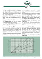
CE The angle has to be checked at each joint separately and the largest angle α1 or α2 has to stay within the allowable range. The resulting total angle β is not relevant for the selection of the shafts, as long as the two angles α1 and α2 are within their limits. These rules also apply analogously for single joints. The continuously allowable angular misalignment is about 1 degree. However, in the interest of long life this value should be kept as low as possible. For transient conditions (eg. engine starting and stopping, very rough sea etc.) up to 3 degrees are allowable. For shock situations...
Open the catalog to page 7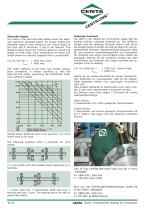
CE Allowable Speed The value in the technical data tables shows the absolute maximum allowable speed. For longer lengths the allowable speed is also limited by the critical speed of the tube and if necessary it has to be reduced. The diagram below shows the limiting values for speed and length of shaft sizes. Each combination of speed and length below the relevant diagonal lines is permissible. e.g. for size 48: n = 1250 rpm, thus: LGmax = 3400 mm. The radial stiffness of the links has hereby already been considered. A further condition is, that the bearings and shafts, supporting the CENTALINK...
Open the catalog to page 8
Technical Data Technische Daten CENTALINK CENTALINK Dyn Torsional Stiffness / * Dyn. Drehsteifigkeit Tdyn links links tube Clinks is stiffness of 2 sets of links Ctube is stiffness of 1 m (1000 mm) tube Rohrlange L in [mm] Clinks ist Steifigkeit fur zwei Gelenke Ctube ist Steifigkeit fur ein Meter Rohr Balancing The common balancing quality for U-joint-shafts is Q16 according VDI 2060. If not agreed differently, the CENTALINK-shafts are balanced as follows: a) flanges, flangehubs and inner part to quality Q6.3 b) the links to quality Q16. The links for the CENTALINK consist of forged aluminium alloy...
Open the catalog to page 9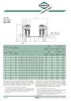
Series Baureihe CL-FF CENTALINK Size CENTALINK Grosse The series FF is the normal series and includes 2 flanges, which can be similar or different in design. Furthermore, if required, standard flanged hubs (page 12) or other special hubs, flanges or adapters can be provided. Die Bauform FF ist die Normalbauform und sie beinhaltet 2 Flansche, die gleich oder unterschiedlich ausgebil-det sein konnen. Dazu kommen dann, je nach Bedarf, Standardflanschnaben (siehe Seite 12) oder sonstige fallspezifische Naben, Flansche oder Adapter. * Die AnschluBmaBe entsprechen der DIN-Norm. Die Dimensionierung...
Open the catalog to page 10
Series Baureihe CL-F0 CENTALINK Size CENTALINK Grosse For series FO a standard flange on one side is intended, while on the other side an existing plain flange can be used. In order to ensure the necessary space for movement is available, the axial bushes are elongated. Thus specially tailored series can be easily designed. * The connecting dimensions are to metric standards. It is important that the value of clamping force is checked to ensure that the torque can be transmitted. If necessary larger standard flanges can be used. When using CENTA flanged hubs the torque capacity is increased using...
Open the catalog to page 11All CENTA POWER TRANSMISSION catalogs and technical brochures
 CENTAFLEX® -E
6 Pages
 CENTAFLEX-B
8 Pages
 CENTAFLEX-A
36 Pages
 CENTADISC-T
1 Page
 CENTADISC-M
8 Pages
 CF-RS
CF-RS6 Pages
 CF-RV
CF-RV8 Pages
 CF-T
CF-T14 Pages
 CF-X
CF-X8 Pages
 CJ
CJ2 Pages
 CM-B
CM-B8 Pages
 CM-G
CM-G4 Pages
 CM-HTC
4 Pages
 CM-S
CM-S24 Pages
 CS-V
CS-V12 Pages
 CX-K
CX-K18 Pages
 CX-SEC
108 Pages
 CX-Test
9 Pages
 CX-TT
CX-TT14 Pages
 CX-V
CX-V20 Pages
 CENTADISC-C
17 Pages
 CENTA-SCS
15 Pages
 Centa Carbon fiber technology
12 Pages
 CENTAMAX - B
8 Pages


- Flexible coupling
- Shaft shaft coupling
- Flange coupling
- Torque coupling
- Rigid coupling
- Sleeve coupling
- Compact coupling
- Motor shaft coupling
- High-torque coupling
- Double-disc coupling
- Pump coupling
- Gear coupling
- Custom-made coupling
- Elastomer coupling
- ATEX coupling
- Double coupling
- High-speed coupling
- High load capacity coupling
- Non-lubricated coupling
- Generator coupling