
- Catalogs
- Cemp S.r.l.
- INDUSTRIAL HAZARDOUS AREA ELECTRIC MOTORS IE1, IE2, IE3, IE4

INDUSTRIAL HAZARDOUS AREA ELECTRIC MOTORS IE1, IE2, IE3, IE4

INDUSTRIAL HAZARDOUS AREA ELECTRIC MOTORS IE1, IE2, IE3, IE4
The document provides an in-depth overview of industrial electric motors designed for hazardous areas, focusing on efficiency classes IE1 to IE4. It includes essential engineering formulae, standards, and specifications relevant to motor drives and protection against explosions.
This section outlines the standard SI units and conversion equations used in the document, covering measurements such as distance, area, volume, and various physical properties like force, pressure, and energy.
Key formulae for calculating power, torque, and moment of inertia for motor drives are provided, including equations for power input/output, torque conversion, and speed ratios.
The document lists international and EU standards for electrical rotating machines, including IEC and CENELEC standards for efficiency, protection types, cooling methods, and noise emission.
This section details the types of protection methods for electrical apparatus in explosive atmospheres, including oil immersion, pressurized apparatus, sand filling, and flameproof enclosures. It also covers protection methods for flammable dusts and electric motors.
Explains the classification of hazardous areas into zones based on the likelihood of explosive atmospheres, as per European directive 1999/92/EC. Zones are categorized for both gas and combustible dust presence.
Equipment is classified into categories based on protection levels, with specific categories for mines and surface installations. The document also discusses enclosure groups and temperature classes for gas atmospheres.
Electrical apparatus is classified into six temperature classes based on maximum surface temperatures, which are critical for preventing ignition in explosive atmospheres.
Combustible gases and vapours are classified by ignition temperature and explosive capacity. Equipment markings indicate protection mode, enclosure group, and temperature class, which determine installation zones. The responsibility for equipment choice lies with the user, not the supplier. Cemp® products have temperature classes ranging from T85°C to T150°C.
Protection against flammable dust considers the dust's flash point in both cloud and layer forms. The motor's surface temperature must be below the reference ignition temperature, calculated as the lower of two values: 2/3 of the cloud ignition temperature or the layer ignition temperature minus 75K.
According to IEC EN 60079-0, equipment used in explosive atmospheres must have an EPL suffix, indicating the probability of becoming an ignition source. EPL helps differentiate between explosive atmospheres.
Directive 1999/92/EC defines the connection between danger zones and equipment categories. Protection modes and motor categories are specified by construction standards. Equipment categories range from very high to normal protection levels, depending on the likelihood of becoming an ignition source.
Cemp® motors are available in IE1 to IE4 versions, with efficiency levels defined by IEC 60034-30. Efficiency is measured according to IEC 60034-2-1 requirements. Tables provide nominal efficiency limits for different frequencies and motor types.
The motors comply with standards for use in safe or potentially explosive areas, in line with the ATEX directive. Users are responsible for area classification and motor choice. Certificates of conformity are issued by Notified Bodies and can be accessed online.
The document provides detailed specifications and characteristics of various motor types, including explosion-proof, non-sparking, and mining applications. It covers both standard and special features, installation guidelines, and nomenclature for different series.
The motors are available in single and two-speed versions, with frame sizes ranging from 63 to 355 mm and output power from 0.09 to 375 kW. They are designed for various applications, including standard, hoist, and mining, with different enclosure groups and protection methods.
Motors comply with IEC and ATEX standards for use in explosive atmospheres with gas and dust. They feature flameproof and increased safety terminal boxes, and are available in efficiency levels IE1 to IE4.
Motors are totally enclosed, fan-cooled, with IP55 frame and IP65 terminal box. They include class F insulation, anti-corrosion components, and options for special electrical and mechanical variants.
Suitable for outdoor and industrial environments, with mechanical protection classified by IP codes. Special designs are available for on-deck and oil-protected flange installations.
The document explains the coding system for motor series, application types, motor characteristics, frame sizes, and mounting options, providing examples for both Classic and Premium series.
1. Fixed Bearings: Applications requiring zero axial play must specify this during the order phase.
2. Cooling: Motors are air-cooled with external surface ventilation (IC 411). Standard motors have a radial flow fan for reversible rotation. Forced ventilation is available for frame sizes 100 to 315.
3. Protection Ratings: IP ratings indicate protection against foreign bodies and water. IP55 offers standard protection, while IP56 and IP66 provide special designs for enhanced protection.
1. Materials: Key components include cast iron frames, steel fan covers, and aluminum or thermoplastic fans. Shafts are made of steel C45, and rotors are squirrel cages in pressure-cast aluminum.
2. Painting: Components are sandblasted and painted with polymerized epoxy polyester powder, offering high resistance to corrosion and chemicals.
1. Low Temperature Version: Motors are designed for temperatures as low as -50°C to -60°C, with flameproof certificates.
2. Anti-Condensation Heating: Strip heaters or low voltage power can prevent condensation. Heaters must be turned off during motor operation.
1. Shaft Ends: Comply with IEC 60072, equipped with tapped holes for pulleys and couplings.
2. Balancing and Vibration: Motors are dynamically balanced to vibration grade “A” (normal) or “B” (reduced) for quiet operation.
1. Construction: Integrated brake motors come with a single ATEX certificate. The brake is enclosed with Ex db IIB or IIC protection and IP65 mechanical protection.
2. Operation: The brake system includes a magnet, counter-magnet, braking disk, and toothed hub. The brake locks the motor shaft when not powered.
3. Braking Torque Calibration: Motors are supplied with calibrated brakes, with special calibration available on request.
1. Noise Levels: Measured according to IEC 60034-9, with sound pressure levels provided for frame sizes.
2. Coupling and Belt Drives: Elastic couplings are permissible, and slide rails are used for belt tensioning.
The document provides detailed specifications for a range of motor frame sizes, focusing on integrated brakes and bearing systems. Frame sizes from 80 to 355 are covered, with specific models like GR4 to GR10 mentioned for different frame sizes. The static braking torque, air gap, on-off braking time, number of disks, maximum speed, and power requirements are specified for each frame size.
Brakes are available in both AC and DC versions, with the option for a manual release on request. The document lists the static braking torque and other technical data for each brake model.
Standard motors are equipped with radial deep groove ball bearings or open bearings with grease nipples. The document details lubrication requirements and seal specifications to prevent dust and water penetration. It also provides a table of standard and special bearings, including time intervals for lubrication and the amount of grease required.
The permissible radial and axial loads on the shaft with standard bearings are detailed, considering factors like frequency, temperature, and motor life expectancy. The document provides tables for permissible radial and axial loads for different frame sizes and pole numbers.
The standard design includes four basic versions, with options for additional terminal boxes or motors without terminal boxes. The position of the terminal box and terminals is adjustable, and the document specifies cable entry positions and requirements for motors with thermodetectors or heaters.
The document outlines standard operating conditions, including rated outputs, voltage, frequency, and ambient temperature. It specifies the motors' ability to operate at different temperatures and altitudes, with adjustments to rated output as necessary. The document also covers speed, direction of rotation, and tolerances according to IEC standards.
Performance data includes rated speeds, direction of rotation, and efficiency. The document provides tables for no-load speed at different frequencies and pole numbers, as well as tolerances for electrical data.
The document outlines the specifications for motors, focusing on efficiency, power factor, insulation, temperature rise, duty types, and connection diagrams. Efficiency and power factor are measured at rated output at 50Hz. Insulation materials are selected to protect against aggressive environments, adhering to IEC 60085 standards with classes F and H. Temperature rise limits are specified for different insulation classes, with standard motors operating within class B limits.
Various duty types are defined according to IEC 60034-1, including continuous running (S1), short-time duty (S2), intermittent periodic duty (S3), and continuous operation periodic duty (S6). Each duty type has specific operational guidelines, such as recommended operating times and cooling periods.
Three-phase motors can be connected using star or delta methods, with specific configurations for single-speed and two-speed motors. Star-delta starting is used to reduce starting current and torque. Single-phase motors have two windings connected to a capacitor, with reversible rotation.
Motors are equipped with protection devices to prevent thermal overloads, including bimetallic devices, PTC temperature sensors, and PT 100 thermometric resistors. These devices ensure safe operation under various conditions, including frequency converter use.
Motors are certified for use with variable speed drives, requiring correct sizing and earthing to avoid bearing currents. The document provides guidelines for operating speeds, torque values, and insulation requirements when using frequency converters.
The document includes detailed performance data for three-phase motors at 400V 50Hz, covering rated output, speed, current, efficiency, power factor, torque, and noise levels. This data is essential for selecting the appropriate motor for specific applications.
The document provides detailed specifications for various motor types, including dimensions and configurations for different frame sizes and applications. It includes data for IE3 and IE4 motors, specifying dimensions for frame sizes ranging from 80 to 355, and details on motor types such as LF.
Instructions for selecting and applying products and components are outlined, emphasizing customer responsibility for ensuring product safety and suitability for intended use. Links to application considerations and terms of sale are provided.
The document lists spare parts for standard and mining application motors, as well as motors with brakes and ventilated brakes. Parts are categorized by motor type and frame size, with specific components such as end caps, grease nipples, bearings, terminal boxes, and cooling fans detailed.
Notes on trademarks and legal disclaimers are included, clarifying ownership and control of various trademarks. The document also provides contact information for Cemp offices in Italy, Germany, and France.
The tables in the document provide specific measurements and configurations for motor components, including dimensions and part numbers for different motor types and applications. These tables are essential for understanding the precise specifications and requirements for each motor type.
Catalog excerpts

PRODUCT CATALOG INDUSTRIAL HAZARDOUS AREA ELECTRIC MOTORS IE1, IE2, IE3, IE4 JULY 2022 | GLOBAL
Open the catalog to page 1
TABLE OF CONTENTS (Click on each page title below to navigate the page.) SI units and conversion equations Engineering formulae for motor drives Standards and specifications Protection against explosions in dangerous areas Efficiency IE1, IE2, IE3, IE4 Range of motors Common main characteristics Main options Nomenclature Installation and applications Low temperature version and anti-condensation heating Materials, painting and nameplate Shaft ends, balancing, vibrations, noise level coupling and belt drives Brake motors Bearing system Permissible radial loads on the shaft with standard bearings...
Open the catalog to page 2
0.1 SI UNITS AND CONVERSION EQUATIONS Table 0A Description Unit symbol Unit name Angular velocity Angular acceleration Pressure Mechanical stress Work done Thermal quantity 9.81 Nm = 1 kgfm 1 Nm = 0.102 kgfm Watt Dynamic viscosity Kinematic viscosity Electric current Electric voltage Electric resistance Electric conductivity Electric capacity Magnetic flux density Magnetic field strength Magnetic flux Temperature difference
Open the catalog to page 3
0.2 ENGINEERING FORMULAE FOR MOTOR DRIVES = power input = ͞ U • I • cos ϕ • √3 • 10 -3 [kW] = power output = P1 • η [kW] Where: U = voltage [ V ] I = current [ I ] cos ϕ = power factor η = efficiency Power requirements of some applications Lifting: P = m • v • 9.81 • 10-3 [kW] η Rotation: P = M • n [kW] 9550 • η Fan and pump drives: P = H • Q [W] η Where: P = power [kW] m = mass [kg] v = speed [m/s] n = rotational speed [min-1] η = efficiency M = torque [Nm] Q = output [m3/s] H = head [N/m2] Torque from motor power M = 9550 • P2 [Nm] n Where: P2 = motor output [kW] n = motor speed Conversion...
Open the catalog to page 4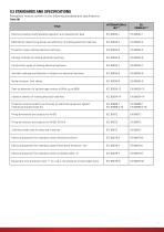
0.3 STANDARDS AND SPECIFICATIONS Flameproof motors conform to the following standards and specifications: Table 0B TITLE INTERNATIONAL IEC®* Electrical rotating machines/rated operation and characteristic data Methods for determining losses and efficiency of rotating electrical machines Protection types rotating electrical machines Cooling methods of rotating electrical machines Construction types of rotating electrical machines Terminal markings and direction of rotation for electrical machines Noise emission, limit values Start-up behaviour of squirrel-cage motors at 50Hz up to 660V Vibration...
Open the catalog to page 5
0.4 PROTECTION AGAINST EXPLOSIONS IN DANGEROUS AREAS 0.4.1 TYPES PROTECTION The use of an electrical apparatus in potentially explosive atmospheres is quite usual today. This equipment has to be manufactured in such a way that there is no risk of explosion. An explosion occurs when of the three following conditions happen: • Presence of a potentially explosive atmosphere; • Possibility of transmission of the explosion; • Existence of an ignition source. The recognized types of protection eliminate one of these conditions and thus make an explosion impossible. Protection methods for GAS Two types...
Open the catalog to page 6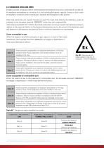
0.4.2 DANGEROUS AREAS AND ZONES Dangerous areas include any area in which explosive atmospheres may occur under specific conditions. An explosive atmosphere is a mixture of air and combustible gases, vapours, fumes or dust under atmospheric conditions where combustion expands itself (explosion) after ignition. Only local authorities can classify hazardous areas. The users shall classify the hazardous areas as indicated in the European directive 1999/92/EC under their own responsibility. International standards IEC®* 61241-10 provide instructions on how to classify the hazardous areas in relation...
Open the catalog to page 7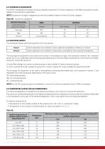
0.4.3 APPARATUS CLASSIFICATION The ATEX®* 2014/34/EU European Directive classifies equipment into three categories, with differing protection levels, related to the protection guaranteed. NOTE: Equipment of higher categories can also be installed instead of those of a lower category. Table 0D - Equipment categories PROTECTION LEVEL guaranteed by the equipment Category Combustible Dust Category Very high 0.4.4 ENCLOSURE GROUPS The standards classify electrical equipment into two groups. Group I electric apparatus to be installed in mines or galleries susceptible to firedamp or coal dust. electric...
Open the catalog to page 8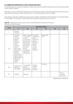
0.4.6 COMBUSTION TEMPERATURES OF GASES, VAPOURS AND GROUPS Combustible gases and vapours are divided into classes according to their ignition temperature and into groups according to their explosive capacity. Markings on motors and other electrical equipment with the symbols used to indicate the protection mode, the enclosure group, and the temperature class, indicate the zone in which such equipment can be installed. The indications contained in table 0F are shown only as an example. Classification of the substances is not the responsibility of the supplier of the equipment. Responsibility for...
Open the catalog to page 9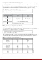
0.4.7 TEMPERATURE FOR ATMOSPHERES WITH COMBUSTIBLE DUSTS The flash point of the dust must be taken into account in providing protection against flammable dust, in both the cloud form and in layers. The surface temperature of the enclosure indicated on the motor nameplate must be less than the reference ignition temperature. The reference temperature is the lowest between the two values thus calculated: TS1 = 2/3 Tcl (Tcl = ignition temperature of the cloud of dust) TS2 = T5mm – 75K (T5mm = ignition temperature of a 5mm layer of dust). Tamm = lowest between TS1 and TS2. Dust ignition temperature...
Open the catalog to page 10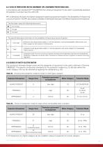
0.4.7 LEVEL OF PROTECTION FOR THE EQUIPMENT (EPL, EQUIPMENT PROTECTION LEVEL) In accordance with standard IEC®* EN 60079-0 the marking of equipment to be used in a potentially explosive atmosphere must also have the suffix EPL. EPL is defined as the level of protection assigned to electrical equipment based on the probability of it becoming a source of ignition. The EPL also makes it possible to distinguish between the different explosive atmospheres. The first letter makes the following distinctions: M The second letter gives information on the probability of becoming a source of ignition: protection...
Open the catalog to page 11All Cemp S.r.l. catalogs and technical brochures
 EXPLOSION PROOF BRAKE MOTORS
6 Pages