T5-LVDT/50-24
1 /4Pages

T5-LVDT/50-24
1 /4Pages
Catalog excerpts

CEMB S.p.A. - 23826 MANDELLO DEL LARIO (LC) I - Via Risorgimento 9 Tel. (+39)0341/706.111 - Telefax (+39)0341/735.678 www.cemb.com e-mail: [email protected] FUNCTION The transducer T5-LVDT/25/24 is used for performing the measurement of Absolute Displacement, the measurement is made by means of a position transducer system based on a linear variable differential transformer (LVDT) by mounting the transducer body on a fixed point and positioned so that the sensor tip of transducer T5-LVDT/50 presses permanently against one end of the movable part of the machine casing. The as picked-up signal is sent to the adapter part AD1-BOX (signal converter situated downstream of the transducer), which makes it suitable for processing by one CEMB T5 unit. PRINCIPLE OF OPERATION A rod in close contact with the movable part to be checked is strictly integral with a magnetic core moving within a fixed coil inside the transducer sensor body. The coil has one primary winding and two secondary windings connected in opposing phase; the output signal (secondary winding) is proportional to the mechanical displacement of the core and should, therefore, be sent to an adapter module (AD1) which makes it suitable for subsequent processing by CEMB instruments, of the “T” series.
Open the catalog to page 1
TECHNICAL CHARACTERISTICS The sensor part carries a removable cover at the top. After removing this cover, it is possible to read the mechanical value of turbine casing expansion on a graduated scale.
Open the catalog to page 2
TRANSDUCER POSITIONING Refer to drawing Nr. 55348. FOREWORD The sensor part carries a removable cover at the top. After removing this cover, it is possible to read the mechanical value of the displacement on a graduated scale. The transducer tip is fitted with a protective cap to protect against damage during transport. Hence such cap should be removed during assembly. The tip is held firmly in contact with the movable part of an internal spring device which also provides a preloading stroke of 3.0 mm of the tip. OPERATIONS TO Remove the protective cap from the tip and separate the sensor part...
Open the catalog to page 3All CEMB catalogs and technical brochures
 ER95 PLUS
4 Pages
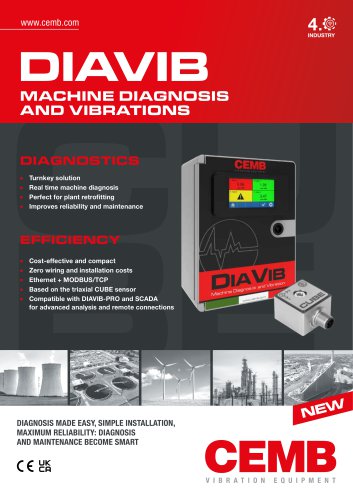 DIAVIB
2 Pages
 N130-GL
4 Pages
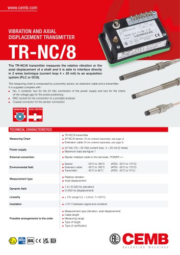 TR-NC/8
4 Pages
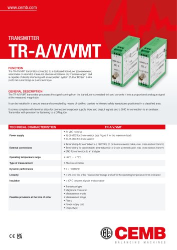 TR-A/V/VMT
2 Pages
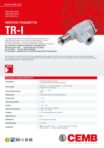 TR-I
TR-I2 Pages
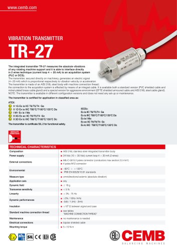 TR-27
TR-272 Pages
 TR-26
TR-262 Pages
 TR-PRO
2 Pages
 AL30
AL304 Pages
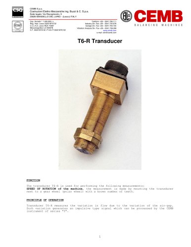 T6-R
T6-R3 Pages
 M16
M162 Pages
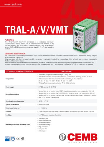 TRAL-A/V/VMT
2 Pages
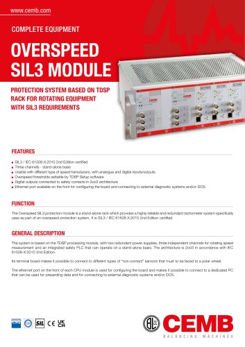 TDSP OVERSPEED
4 Pages
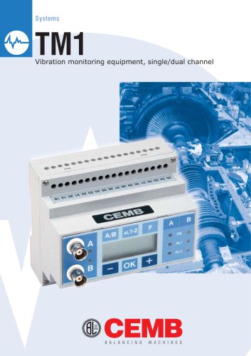 TM1
TM14 Pages
 TDSP
TDSP12 Pages
 TD-2
TD-24 Pages
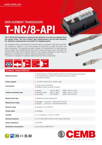 T-NC/8-API
4 Pages
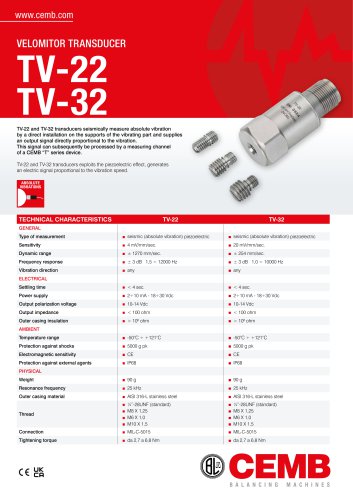 TV-22
TV-222 Pages
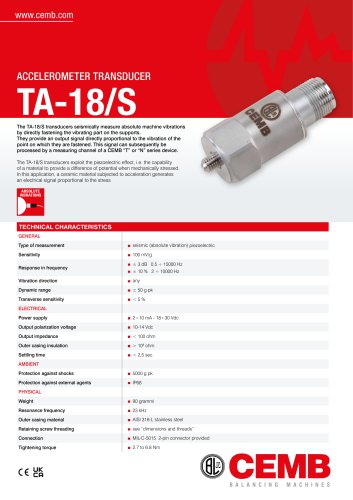 TA-18
TA-182 Pages
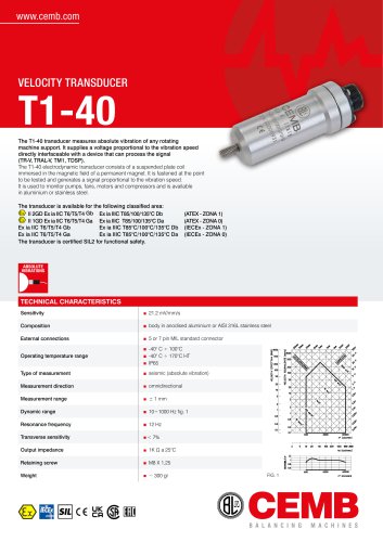 T1-40
T1-402 Pages
 CUBE
CUBE4 Pages
 DIAVIB - PRO
4 Pages
 2-HIT
2-HIT4 Pages
 ER100GT
4 Pages
 SMX70 LL
4 Pages
 SMX70
SMX704 Pages
 SMX50
SMX504 Pages
 SMX40
SMX404 Pages
 DWA1100 TROLLEY
4 Pages
 DWA1100 TRUCK LIGHT
4 Pages
 DWA1100 TRUCK
4 Pages
 Argos Drivethru
2 Pages
 SMT30
SMT304 Pages
 SMT56
SMT564 Pages
 DWA1100 HYBRID LIGHT
4 Pages
 DWA1100 HYBRID
4 Pages
 DWA1100 LIGHT
4 Pages
 DWA1100
4 Pages
 DWA2500
4 Pages
 KIT ADAS CCD
4 Pages
 ARGOS
ARGOS2 Pages
 CEMB Truck balancer C218
6 Pages
 ER65
ER654 Pages
 ER90 EVO
4 Pages
 ER85
ER854 Pages
 ER70 EVO
4 Pages
 ER80
ER804 Pages
 ER63
ER634 Pages
 ER15
ER154 Pages
 ER60 PRO
4 Pages
 ER10 PRO
4 Pages
 Balancing machines
2 Pages
 N330
N3304 Pages
 SMT60/60R
2 Pages
 TB7
TB76 Pages
 Original CEMB adaptors
8 Pages
 CABLES & CONNECTORS
4 Pages
 AL10
AL102 Pages
 N130
N1304 Pages
 T-NC
T-NC2 Pages
 DWA3500
4 Pages
 PAGURO P2
2 Pages
 PAGURO P1
4 Pages
 ER10
ER104 Pages
 Dynamic tool balancer
6 Pages
 CEMB Moto balancer K22
4 Pages
 CEMB On-car balancer L88
4 Pages
 CEMB Truck balancer C202/SE
4 Pages
 CEMB Truck balancer C212
4 Pages
 CEMB Truck balancer C210
4 Pages
 CEMB Truck balancer C206
4 Pages
 CEMB Wheel balancer C30
4 Pages
 N600 - PORTABLE EQUIPMENT
4 Pages


Archived catalogs


- Connector
- Data connector
- Proximity switch
- Acceleration sensor
- Cylindrical proximity sensor
- Piezoelectric accelerometer
- Straight connector
- Cable connector
- CEMB balancing machine
- Displacement transducer
- CEMB dynamic balancing machine
- Linear displacement sensor
- Triaxial acceleration sensor
- CEMB horizontal balancing machine
- Measurement monitoring module
- Compact accelerometer
- Acceleration sensor with analog output
- Temperature monitoring module
- CEMB tire changer
- Threaded proximity sensor