


- Company
- Products
- Catalogs
- News & Trends
- Exhibitions
XY25XS

XY25XS
Overview
This document provides the standard properties, test procedures, and optional configurations for the XY25XS actuator developed by CEDRAT TECHNOLOGIES. It details the technical conditions under which the actuator's performance is measured and guaranteed.
Technical Conditions of Use and Measurement
- Mounting Conditions: Free-free (actuator not fixed) and Blocked-free (actuator fixed to an infinitely stiff mechanical support).
- Excitation Types: Quasistatic excitation with AC voltage between -20 V and 150 V at 1 Hz; Harmonic excitation with 0.5 Vrms sinusoidal voltage from 0 to 100 kHz; Maximum harmonic excitation defined by max displacement at resonance frequency.
- Measurement Methods: Displacement measured via laser interferometer or capacitive displacement sensor; Admittance measured using HP 4194 A or Cypher C60 impedance analyzers.
- Environmental Conditions: Ambient temperature between 15-25°C and dry air with humidity below 50% relative humidity.
- Note: Deviations from these conditions may cause temporary or permanent changes in actuator properties; users are advised to consult CEDRAT TECHNOLOGIES before non-standard use.
Factory Tests Conducted
- Electrical admittance versus frequency (free-free condition)
- Displacement versus input voltage
- Sensor gain and linearity
- Step response in closed loop
- Stability in closed loop
Available Options
- Strain Gauges (SG)
- Eddy Current Displacement Sensor (ECS)
- Specific Interface (SI)
- Non-magnetic version (NM) - optional
- Vacuum compatibility (VAC)
- Specific version or customization (SV)
Key Performance Specifications
| Property | Measurement Condition | Unit | Nominal | Minimum | Maximum |
|---|---|---|---|---|---|
| Maximum No Load Displacement (Tx, Ty) | Quasistatic excitation, blocked-free | µm | 25 | 23 | 29 |
| Out of Plane Z Displacement | Quasistatic excitation, blocked-free | µm | 0.50 | 0.30 | 0.70 |
| Maximum Parasitic Z Rotation | Quasistatic excitation, blocked-free | µrad | 50.00 | 42.50 | 57.50 |
| Maximum Parasitic XY Rotation | Quasistatic excitation, blocked-free | µrad | 10.00 | 8.50 | 11.50 |
| Blocked Force | Quasistatic excitation, blocked-free | N | 40 | 32 | 48 |
| Stiffness | Quasistatic excitation, blocked-free | N/µm | 2.50 | 2.00 | 2.75 |
| Unloaded Resonance Frequency | Harmonic excitation, blocked-free | Hz | 3000 | 2400 | 3450 |
| Unloaded Response Time | Quasistatic excitation, blocked-free | ms | 0.17 | 0.15 | 0.19 |
| Capacitance (per electrical port) | Quasistatic excitation, blocked-free | µF | 0.50 | 0.45 | 0.65 |
| Resolution | - | nm | 2.50 | - | - |
| Height (Z axis) | - | mm | 20 | 19.90 | 20.20 |
| Dimensions (X & Y) | - | mm | 50×50 | - | - |
| Mass | - | g | 80.0 | - | - |
Mechanical and Electrical Interfaces
- Mechanical Interface (Payload): One Ø17 mm hole plus four Ø2.2 mm holes on Ø20 mm circle.
- Mechanical Interface (Frame): Four Ø2.8 mm holes on a 45 mm pattern.
- Electrical Interface: Two RG178B/U coaxial cables with Harwin connectors or two PTFE insulated AWG30 wires (100 mm long) with Ø1 banana plugs.
Critical Notes and Recommendations
All properties are guaranteed only within the specified technical conditions. Using the actuator outside these conditions may cause temporary or permanent degradation. It is recommended to contact CEDRAT TECHNOLOGIES for guidance before applying non-standard conditions.
Catalog excerpts

copyright © cedrat technologies i 11/2017 www.cedrat-technologies.com | [email protected] / ^ CEDRAT ^ TECHNOLOGIES \ | Innovation in Mechatronics > TABLE OF STANDARD PROPERTIES OF USE AND MEASUREMENT The properties defined in the table below, are set up according to the technical conditions of use and measurement. These properties are warranted within their variation range and in compliance with the standard technical conditions of use. STANDARD TECHNICAL CONDITIONS NOMINAL VALUES Notes Sensor options Mastered motions Max. no load displacement Out of plane Z displacement Max. parasitic Z rotation Max. parasitic XY rotation Blocked force Stifness Unloaded resonance frequency (in the actuation's direction) Unloaded response time Capacitance (per electrical port) Resolution Heigth (Z axis) Dimensions (X&Y) Mass Standard mechanical interface (payload) Standard mechanical interface (frame) Standard electrical interface Standard electrical interface SG, ECS TX, TY Quasistatic excitation, blocked-free (Tx, Ty) Quasistatic excitation, blocked-free Quasistatic excitation, blocked-free Harmonic excitation, blocked-free, on the admittance curve Quasistatic excitation, blocked-free Quasistatic excitation, blocked-free, on the admittance curve 1 0 17 mm hole + 4 02.2 mm on 0 20 mm 4 0 2.8 mm holes on [] 45 2 RG178B/U coaxial cables with Harwin connectors 2 PTFE insulated AWG30 wires 100 mm long with 0 1 banana plug > PROPERTIES STANDARD TECHNICAL CONDITIONS OF USE AND MEASUREMENT Free-free : Blocked-free : Quasistatic excitation : Harmonic excitation : Max. harmonic excitation : Displacement measurement : Admittance measurement : Environment : The actuator is not fixed The actuator is fixed to a mechanical support assumed infinitely stiff AC voltage between -20 and 150 V at 1 Hz Voltage of 0.5 Vrms, sinusoidal mode from 0 to 100 kHz Voltage defined by the measurement of max. displacement, sinus at resonance frequency Laser interferometer, capacitive displacement sensor HP 4194 A or Cypher C60 electrical impedance analyser Ambient temperature (15-25°C) and dry air (Humidity < 50 % rH) Any technical conditions of use, different from those defined above, can lead to temporary or definitive alterations of properties. Thank you to contact CEDRAT TECHNOLOGIES before using actuators under non standard technical conditions. > FACTORY TESTS CARRIED OUT 0 Test 1 : Electrical admittance vs. Frequency, free-free 0 Test 2 : Displacement vs. input voltage > OPTIONAL EXTRA FACTORY TESTS 0 Test 3 : Gain and linearity of the sensor 0 Test 4 : Step response in closed loop 0 Test 5 : Stability in closed loop > AVAILABLE OPTIONS 0 [ SG ] Strain gauges □ [ NM ] Non-magnetic 0 [ ECS ] Eddy current displacement sensor 0 [ SV ] Specific version / customization CEDRAT TECHNOLOGIES • 59 Chemin du Vieux Chene • Inovallee • 38246 MEYLAN Cedex France Tel. : +33 (0)4 56 58 04 00
Open the catalog to page 1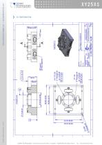
copyright © cedrat technologies i 11/2017 www.cedrat-technologies.com | [email protected] z ^ CEDRAT * TECHNOLOGIES X l Innovation in Mechatronics > 2D CONFIGURATION XY25XS CEDRAT TECHNOLOGIES • 59 Chemin du Vieux Chene • Inovallee • 38246 MEYLAN Cedex France Tel. : +33 (0)4 56 58 04 00
Open the catalog to page 2All CEDRAT TECHNOLOGIES catalogs and technical brochures
 DTT35XS-SI-2
3 Pages
 XY Piezo stages heritage
8 Pages
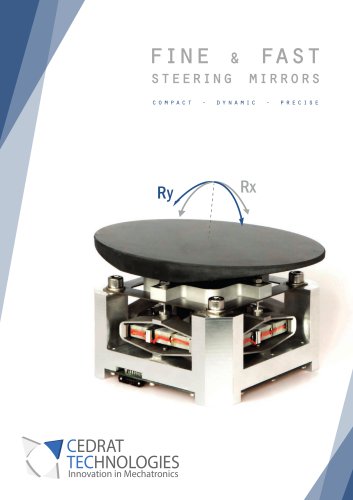 Fine and fast steering mirrors
10 Pages
 Synchrotron Brochure
10 Pages
 DTT35XS
3 Pages
 TT60SM
3 Pages
 APA600M
2 Pages
 APA400M
2 Pages
 APA200M
2 Pages
 APA150M
2 Pages
 APA100M
2 Pages
 APA60SM
2 Pages
 APA40SM
2 Pages
 APA60S
2 Pages
 APA50XS
2 Pages
 APA35XS
2 Pages
 APA150XXS
2 Pages
 PPA20M
2 Pages
 PPA40M
2 Pages
 PPA40L
2 Pages
 PPA60L
2 Pages
 PPA80L
2 Pages
 PPA120L
2 Pages
 PPA40XL
2 Pages
 PPA80XL
2 Pages
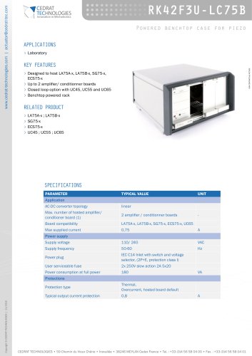 RK42F3U-LC75B
2 Pages
 CA45
CA454 Pages
 LA75A
LA75A4 Pages
 LA75B
LA75B4 Pages
 LA75C
LA75C3 Pages
 SA75A
SA75A3 Pages
 SA75B
SA75B3 Pages
 SA75D
SA75D3 Pages
 SP75A
SP75A3 Pages
 UC65
UC653 Pages
 UC55
UC553 Pages
 UC45
UC452 Pages
 RK42F3U-LC24
2 Pages
 ECSU10
2 Pages
 ECS75
ECS753 Pages
 ECP1000
2 Pages
 ECP500
2 Pages
 APA30uXS
2 Pages
 PPA10M
2 Pages
 FP7 SONO PROJECT
2 Pages
 ASPIC PROJECT
1 Page
 viper cleansky project
2 Pages
 MISAC PROJECT
2 Pages
 PPSMPAB PROJECT
3 Pages
 AEROPZT PROJECT
2 Pages
 DYNXPERTS PROJECT
1 Page
 E-LIFT3 PROJECT
1 Page
 FluMIn3 projecT
1 Page
 CONTACTLESS TORQUE SENSORS
2 Pages
 MC-SUITE Project
3 Pages




- Power supply unit
- DC power supply
- AC/DC power supply
- Linear actuator
- Electric actuator
- Positioning table
- Translation stage
- Switched-mode power supply
- Motorized positioning table
- Compact actuator
- Precision positioning table
- Tabletop power supply
- Current sensor
- Rack-mount power supply
- Power amplifying integrated circuit
- Ultrasonic transducer
- 2-axis positioning table
- Precision actuator
- Compact positioning table