
- Catalogs
- CDS Cam Driven Systems
- ITP Index table


- Company
- Products
- Catalogs
- News & Trends
- Exhibitions
ITP Index table

ITP Index table
The document details specifications for index tables models ITP 75, 100, 150, 200, and 300. Housing materials range from aluminum alloy for ITP 75-100 to cast iron alloy for ITP 150-300, with finishes like electroless nickel plating and red paint. The tables support 2 to 12 stops and include features such as oversized preloaded tapered-roller bearings, stationary center-post through-holes, and CNC induction hardened cam-profiles. They are lubricated for life with an oil bath and have a guaranteed sealing system. 3D models are available online.
Repeatability is shown in Diagram A, illustrating the relationship between repeatability and dial plate diameter. Table A provides maximum suggested dial plate diameters for each model.
Formulas for calculating axial force (Fa), radial force (Fr), and overturning moment (Mr) on the output flange are provided. An Excel file for sizing applications is available for download.
Inertia values for different models and configurations are provided, with specific order codes for each configuration. Dynamic braking with an inverter is recommended for optimal performance during emergency stops.
Optional features include proximity sensors, phase cams, protection systems, and riser supports. Dimensions for various models and wiring connections for E-CAM electronic phase cams are also provided.
Technical specifications include tolerances and dimensions for mechanical components, such as:
- Tolerances: EN 22768-1D ± 0.015 mm, Rp ± 0.011°
- Threaded holes: M10 and M12 with specific depth and diameter tolerances
- Concentricity, planarity, and accuracy standards adhering to UNI - ISO 2768-1
The setup and operation of the E-CAM Motor Management System are described, including:
- Integration of an e-cam and e-relay box for motor control
- Connection and disconnection of the motor based on input shaft position
- Use of PLC signals to manage motor start and stop phases
The document adheres to international standards for mechanical tolerances and electronic components, ensuring compliance with UNI - ISO 2768-1 and EN 22768-1D.
For safe operation, using a VFD/inverter for managing e-stops is recommended. Optimizing cycle time and improving system diagnostics through the E-CAM system is also suggested.
- Optimizes cycle time and improves lifetime
- Provides immediate diagnostics and easy tuning
- Ensures accurate and fast motor stops
- Eliminates PLC delays in motor control
Further details are available in a video on the company's website.
The motor stopping system uses two phase cams (A and B) and two sensors (SA and SB). Phase cam A is fixed to the input shaft with a cutout (DW) corresponding to the dwell period of the indexer. Phase cam B is adjustable, and its gap (DS) must be equal to or wider than the cutout in phase cam A.
1. When sensor SA's output is low, the unit is in dwell DW.
2. Phase cam B provides a stop signal to the motor. The adjustable timing bands allow sensor SB to detect the dwell position before sensor SA, indicating the indexer is in dwell.
3. When sensor SB's output goes low, it signals the motor to start decelerating.
4. The motor decelerates and stops in the dwell period.
5. If the motor does not stop correctly, adjust the timing bands of phase cam B to ensure the stop signal is detected earlier.
Diagrams 1 and 2 illustrate the timing sequence and operation. Diagram 1 shows the motor properly stopping in the dwell period, while Diagram 2 shows improper stopping.
Managing motor speed through controlled deceleration rather than coasting to a stop is crucial.
CDS synchronous torque limiters provide maximum protection by detecting overloads upstream from the indexer. They ensure accurate reset positioning, torque repeatability, and a rigid, backlash-free connection. The LR series is designed for CDS indexers with output flanges and includes components such as a torque adjustment ring, springs pre-loading ring, phase rollers, rotating support flange, and assembly ring. The torque limiter is not a safety device and must be ordered separately.
CDS synchronous torque limiters are designed to provide maximum protection by detecting overloads directly from the intermittent mechanism. They ensure precise calibration of the intervention threshold and repeatability, offering a rigid and backlash-free connection of driven components. These limiters protect against impacts during positioning and overloads during work station pauses.
LR versions are designed for CDS mechanisms with flange output. Key components include:
- (A) Calibration nut for disengagement torque
- (B) Preload and intervention signal ring
- (C) Phase rollers
- (D) Rotating connection ring
- (E) Assembly ring
Note that the torque limiter is not a safety device.
The document includes a table listing various models of torque limiters with specifications such as dimensions and mounting details.
Contact information for GATE Technologies Inc. and its global offices in the USA, China, Germany, and India is provided. The company is highlighted for its expertise in industrial automation products and services, backed by over 70 years of engineering and manufacturing leadership.
Catalog excerpts

INDEX TABLE TAVOLE ROTANTI INDEXATE INDEXIERTE DREHTISCHE TABLES ROTATIVES INDEXEES MESAS GIRATORIAS INDEXADAS 分度转台
Open the catalog to page 1
This catalogue cancels and replaces any preceding issue or revision. The data provided in the catalogue are not binding; in line with our commitment to on-going product improvement, we reserve the right to make changes without prior notice. The technical data not present in this catalog are available from our technical office. When in doubt, you are welcome to download the latest up-to-date version available on our web site: www.cdsindexers.com Importante Questo catalogo annulla e sostituisce ogni precedente edizione o revisione. I dati esposti nel catalogo non sono impegnativi e ci riserviamo...
Open the catalog to page 2
Loads on output flange Carichi sul divisore Charges sur le diviseur Tiempos de ciclo con motorreductor Cycle times with motoreducer Tempi di ciclo motoriduttore Temps de cycle avec motoreducteur Tiempos de ciclo con motorreductor Connection diagram motor Schema collegamento Anschlußpläne Motor motore Schéma de connexions Esquemas de conexión 电机连 接图 moteur motor E-CAM Electronic phase cam E-CAM Camma di fase elettronica E-CAM Elektronischer E-CAM Came de Phasennnocken phase électronique E-CAM Leva de fase electrónica E-CAM wiring connection Schema collegamento...
Open the catalog to page 3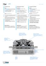
Grandezze: • ITP 75-100 carcassa in lega d’alluminio • ITP 150-200 carcassa in fusione di ghisa, nichelatura chimica • ITP 300 carcassa in fusione di ghisa, verniciatura rosso RAL3000 Größen: • ITP 75-100 Gehäuse aus Aluminiumlegierung • ITP 150-200 Gehäuse aus Gusseisen, vernickelet • ITP 300 Gehäuse aus Gusseisen, lackiert rot RAL3000 • Output dial mounting flange supported by oversized preloaded tapered-roller bearing • Stationary center-post through-hole • Maximum station-to-station accuracy • CNC induction hardened cam-profiles • Oil bath lubrication for life • Guaranteed sealing system...
Open the catalog to page 4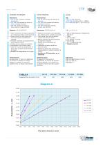
Dimensiones: • ITP 75-100 carcasa de aleación de aluminio • ITP 150-200 carcasa de fundición, nichelatura chimica • ITP 300 carcasa de fundición, pintura roja RAL3000 规格: • ITP 75-100 铝合金外壳 • ITP 150-200 铸铁合金外壳,无电镀镍 • ITP 300 铸铁合金外壳,涂 RAL3000 红漆 DATOS TÉCNICOS Dimension: • ITP 75-100 carcasse en alliage d’aluminium • ITP 150-200 carcasse en fusion de fonte, nickelage chimique • ITP 300 carcasse en fusion de fonte, peinture rouge RAL3000 • Salida de movimiento con brida fijada por cojinete cónico sobredimensionado • Cubo central fijo con gran agujero central lista para ser usado • Máxima precisión...
Open the catalog to page 5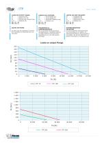
To easily size the application, an Excel file is available for download from our web sites. SIZING SOFTWARE LASTEN AUF DEM TEILGERÄT Fa = Längskraft (N) Fr = Radialkraft (N) Mr = Kippmoment (Nm) b, dr = Abstand (m) Mr = Fr . dr Mr = Fa . b CARICHI SUL DIVISORE Fa = Forza assiale (N) Fr = Forza radiale (N) Mr = Momento ribaltante (Nm) b, dr = Distanza (m) Mr = Fr . dr Mr = Fa . b LOADS ON OUTPUT FLANGE Fa = Axial force (N) Fr = Radial Force (N) Mr = Overturning moment (Nm) b, dr = Distance (m) Mr = Fr . dr Mr = Fa . b PROGRAMMA DI DIMENSIONAMENTO Per un più facile dimensionamento dell’applicazione,...
Open the catalog to page 6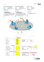
CARGAS EN EL DIVISOR Fa = Fuerza axial (N) Fr = Fuerza radial (N) Mr = Momento de vuelco (Nm) b, dr = Distancia (m) Mr = Fr . dr Mr = Fa . b PROGRAMA DE DIMENSIONAMIENTO Para que el dimensionamiento de la aplicación sea más fácil, es posible utilizar una hoja electrónica en formato Excel, disponible en nuestros sitios Web en la sección de descarga. Motor type 为了更方便的定制应用,可以从我们的 网站直接下载选型 Excel 文件。 Torque limiter PROGRAMME DE DIMENSIONNEMENT Pour un dimensionnement plus facile de l’application, il est possible d’utiliser un fichier électronique en format Excel disponible sur nos sites à la section...
Open the catalog to page 7
Jmax application inertia Jmax inerzia applicazione Jmax Trägheit Anwendung Jmax inertie application Jmax inercia de aplicación Jmax 应用转动惯量 INERTIA INERZIA TRÄGHEIT INERTIE INERCIA 惯量 B Order code Order code Order code Order code Order code Order code Order code Order code Order code Order code Order code Order code Order code Order code Order code Order code Order code Order code Order code Order code • For optimum performance of the unit in the emergency-stop condition, we recommend dynamic braking using an inverter, with minimum deceleration time calculated using our sizing software based on...
Open the catalog to page 8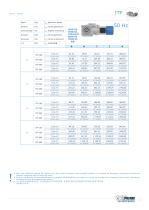
Jmax application inertia Jmax inerzia applicazione Jmax Trägheit Anwendung Jmax inertie application Jmax inercia de aplicación Jmax 应用转动惯量 INERTIA INERZIA TRÄGHEIT INERTIE INERCIA 惯量 H Order code Order code Order code Order code Order code Order code Order code Order code Order code Order code Order code Order code Order code Order code Order code Order code • Pour une utilisation optimal de l’appareil lors des arrêts d’urgence il est conseillé d’utiliser un variateur de fréquence, programmé suivant les donnees indiquees dans la feuille de calcul. • Para un uso óptimo de la unidad durante las...
Open the catalog to page 9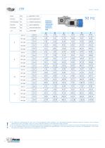
Jmax application inertia Jmax inerzia applicazione Jmax Trägheit Anwendung Jmax inertie application Jmax inercia de aplicación Jmax 应用转动惯量 INERTIA INERZIA TRÄGHEIT INERTIE INERCIA 惯量 B Order code Order code Order code Order code Order code Order code Order code Order code Order code Order code Order code Order code Order code Order code Order code Order code Order code Order code Order code Order code • For optimum performance of the unit in the emergency-stop condition, we recommend dynamic braking using an inverter, with minimum deceleration time calculated using our sizing software based on...
Open the catalog to page 10All CDS Cam Driven Systems catalogs and technical brochures
 HT Ring table
20 Pages
 IG-IGA Roller gear index drives
41 Pages
 TRP Index table
52 Pages
 IT Mechanical index tables
34 Pages
 TR Mechanical index tables
45 Pages
 MHP Rotary parts-handlers
23 Pages
 GT Technical Guide
43 Pages
 CR Cycloidal reducers
20 Pages
 TCR Cycloidal table
20 Pages
 CPC Chain pallet conveyors
52 Pages
 LA Linear actuator
24 Pages
 FTP Ring table
24 Pages
 FT Ring table
24 Pages
 MCR pick & place unit
24 Pages
 EL Part Elevator
28 Pages
 Products brochure
25 Pages
 IP Parallel index drives
26 Pages
 LHP Linear parts-handlers
17 Pages
 CU Tool changer
20 Pages
 CPT Pallet changer
20 Pages
 MUL Linear tool magazine
8 Pages


- Rail conveyor
- Actuator
- Transport rail conveyor
- Belt conveyor
- Horizontal conveyor
- Conveying belt
- Conveyor for the food industry
- Turntable
- Chain conveyor
- Electric rotary table
- Work conveyor
- Industrial conveyor belt
- Manipulator for industrial applications
- Flush grid conveyor belt
- Food conveyor
- Modular conveyor
- Manipulator with gripping tool
- Horizontal rotary table
- Rotary actuator
- Modular conveyor belt