
- Catalogs
- CDS Cam Driven Systems
- GT Technical Guide


- Company
- Products
- Catalogs
- News & Trends
- Exhibitions
GT Technical Guide

GT Technical Guide
Cam Driven Indexers are mechanical devices that convert constant rotary motion into intermittent, dynamically controlled motion. They are valued for their speed, precision, and reliability. The document details various cam-operated mechanisms, including Paradromic, Barrel, and Globoidal types, which are essential in mechanical indexing functions.
Indexing involves moving a mechanical member from an initial to a new position, starting and ending in a rest position. The motion is determined by the cam shape, with types such as Modified Sine Motion, Modified Sine with Constant Velocity, Modified Trapezoid Motion, and Asymmetric Modified Sine Motion, each with unique acceleration and velocity characteristics.
The document provides guidelines on operating modes, capacity, accuracy, and rigidity/stability of index drives, emphasizing the importance of selecting the appropriate motion type based on the mechanism's physical properties.
Guidelines for input systems include lineshafting, reducers, and motors, which are crucial for effective motion transmission within the system.
Protection systems are essential for preventing overloads, with mechanisms acting at both the input and output of the indexer.
Proper lubrication and sealing are vital for maintaining performance and longevity. The document outlines best practices for effective lubrication and sealing.
Selection criteria include mass, mass inertia, effective radius of inertia, dynamic torque, input torque, motor power, and dynamic overload, which are critical for optimal indexer performance.
The guidelines introduce cam-driven systems and their application challenges, recommending consulting engineers for detailed assistance.
This section discusses intermittent function in machinery, characterized by specific laws of motion determined by the cam profile. It covers Modified Sinusoidal Motion, Modified Sinusoidal Motion with Constant Speed Phase, Modified Trapezoidal Motion, and Asymmetric Modified Sinusoidal Motion, with flexibility limited by the mechanism's physical properties.
The number of stops is calculated as S = 360°/β, with CDS Index Drives allowing fractional stops and up to 300 stops.
Index and dwell periods are defined by angles and times, with flexibility limited by the mechanism's physical properties.
The direction of rotation is crucial for synchronization, with Paradromic, Barrel, and Globoidal mechanisms affecting input and output rotation directions.
The document discusses operational modes and specifications for cam devices, focusing on continuous operation and cycle on demand, emphasizing precise timing to optimize performance.
2.1 Continuous Operation
Involves continuous camshaft rotation, enhancing performance through overlapping machine stages.
2.2 Cycle on Demand
Allows flexible control of dwell time, suitable for machines with variable functions.
CDS indexer capacity includes a safety factor of 1.75, with application software assisting in selecting the appropriate indexer.
4.1 Accuracy
CDS precision ensures accuracy, with reports recorded according to ISO 9001 standards.
4.2 Rigidity and Stability
Optimal performance is achieved with specific ratios of indexed mass to pitch radius.
Recommends using CDS adjustable phase cams for cycle control and considering error margins in multi-cycle applications.
Discusses motors with electromagnetic brakes, worm gear reducers, AC, DC, and servo motors, each with specific features and applications.
Protection systems include current/torque limiters and motor controllers to prevent overloads.
Figures illustrate motor types and overload protection systems.
Details on grease type, consistency, penetration, and specific weight.
Formulas for mass calculation using parameters like radius and specific weight.
Inertia calculations for masses rotating about their own and offset axes.
Dynamic torque calculations using inertia torque, friction torque, and coefficients.
Input torque and motor power calculations considering motion absorption and efficiency.
Dynamic overload calculations using angular speed and transmission stop time.
Catalog excerpts

CAM DRIVEN INDEXERS TECHNICAL GUIDELINES GUIDA TECNICA CONGEGNI INTERMITTENTI A CAMMA TECHNISCHE ANLEITUNG INTERMITTIERENDE NOCKENGETRIEBE GUIDE TECHNIQUE MECANISMES INTERMITTENTS A CAME GUÍA TÉCNICA PARA DISPOSITIVOS INTERMITENTES DE LEVA
Open the catalog to page 1
This catalogue cancels and replaces any preceding issue or revision. The data provided in the catalogue are not binding; in line with our commitment to on-going product improvement, we reserve the right to make changes without prior notice. When in doubt, you are welcome to download the latest up-to-date version available on our web site: www.cdsindexers.com Importante Questo catalogo annulla e sostituisce ogni precedente edizione o revisione. I dati esposti nel catalogo non sono impegnativi e ci riserviamo il diritto di apportare eventuali modifiche senza darne preavviso, nell’ottica di un miglioramento...
Open the catalog to page 2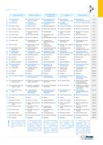
Congegni intermittenti a camma Mecanismes Dispositivos intermittents â came intermitentes de leva Numero delle stazioni Angle de transfert came Cycle intermittent Períodos de ocupación de leva Ciclo intermitente Periodi di impegno camma Ciclo intermittente Frequenza del ciclo intermittente Frèquence cycle intermittent Frecuencia del ciclo intermitente Numero dei principi della camma Frequenz des intermittierenden Zyklus Anzahl der Nockengänge Nombre de principes à Número de principios le came de la leva Index drive code designation Codifica dell’unità intermittente...
Open the catalog to page 3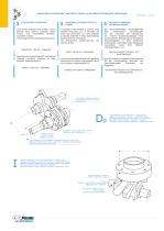
INDEXING ● FUNZIONE INTERMITTENTE ● INTERMITTIERENDE FUNKTION Paradromic - Barrel - Globoidal have become predominant for mechanical indexing functions because of their superior characteristics in Speed - Precision - Reliability I congegni intermittenti a camma sono sistemi meccanici per il controllo del moto che convertono un moto rotatorio a velocità costante in moto intermittente dinamicamente controllato. Tre azionamenti rispettivamente con camma di tipo: Cam Driven Indexers are motion control devices that convert constant rotary motion into intermittent dynamiccontrolled motion. Three types...
Open the catalog to page 4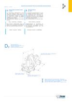
FONCTION INTERMITTENTE ● FUNCIÓN INTERMITENTE MECANISMES INTERMITTENTS A CAME Plane - Cylindrique - Globoïdale Plano, Cilíndrico y Globoidal Velocidad, Precisión y confiabilidad Vitesse - Precision - Fiabilite respectivamente se convirtieron en predominantes en la gestón mecánica de funciones intermitentes por sus características de sont devenus prèdominants dans la gèstion des mouvements intermittents pour leurs caractèristiques èlevées de: Los Dispositivos Intermitentes de Leva son sistemas mecánicos para el control del movimiento que convierten un movimiento giratorio a una velocidad constante...
Open the catalog to page 5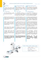
INDEXING ● FUNZIONE INTERMITTENTE ● INTERMITTIERENDE FUNKTION FUNZIONE INTERMITTENTE INTERMITTIERENDE FUNKTION Unter intermittierende Funktion versteht man die Bewegung eines mechanischen Elements von einer Ausgangsstellung zu einer neuen Stellung mit Abfahrt und Anhalt in einer bestimmten Stellung. The motion characteristic of going from one position to a new position is determined by the cam-shape. Le caratteristiche dinamiche del movimento, dalla posizione iniziale alla nuova posizione, vengono determinate dal profilo-camma, definito sulla base della Legge di Moto (L.M.) prescelta. Die dynamischen...
Open the catalog to page 6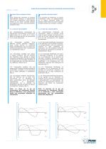
FONCTION INTERMITTENTE ● FUNCIÓN INTERMITENTE Les caractéristiques dynamiques du mouvement d’une position à l’autre sont dètèrminées par le profil de la came, défini sur la base de la loi de mouvement (L.M.) prèsé léctionnée. Las características dinámicas del movimiento, desde la posición inicial hasta la nueva posición, las determina el perfil de la leva, definido sobre la base de la ley del movimiento (L.M.) elegida de antemano. FONCTION INTERMITTENTE FUNCIÓN INTERMITENTE La L.M. Sinusoidal Modificada con tramo a Velocidad Constante, se ha logrado con la introducción de un periodo de velocidad...
Open the catalog to page 7
INDEXING ● FUNZIONE INTERMITTENTE ● INTERMITTIERENDE FUNKTION Il numero delle stazioni definisce il numero totale di arresti che l’uscita del congegno compie durante il suo giro completo ed è, generalmente, un numero intero. Nominato S il numero delle stazioni e β la singola traslazione angolare dell’uscita: Die Anzahl der Stationen bestimmt die Gesamtanzahl der Anschläge des Teilers während einer kompletten Drehung und entspricht normalerweise einer Ganzzahl. S stellt hier die Anzahl der Stationen dar und β das einzelne Winkelschalten des Teilers: Note: CDS Index Drives are available with fractional...
Open the catalog to page 8
FONCTION INTERMITTENTE ● FUNCIÓN INTERMITENTE Nota: CDS fournit egalement des appareits avec un nombre de station non entier, tel que 1.5 stations equivalent à 240° de positionnement angulaire en sortie, comme au delà de 300 station. El numero de paros define la cantidad total de paradas que la salida del dispositivo cumple durante su giro completo y, generalmente, es un número entero. Denominado S el número de paros y β la traslación angular individual de salida: Nota: CDS también suministra con un número de paros no entero como por ejemplo 1.5 paros equivalentes a 240° de emplazamiento angular...
Open the catalog to page 9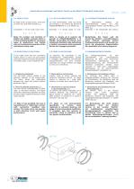
INDEXING ● FUNZIONE INTERMITTENTE ● INTERMITTIERENDE FUNKTION An index cycle, in basic terms, is the sum of Index (t1) and Dwell periods (t2). Un ciclo intermittente, nella sua forma più semplice, è la somma dei periodi di POSIZIONAMENTO (t1) e di PAUSA (t2). Considered T as the total cycle time : Nominato T il tempo totale di ciclo: Im allgemeinen besteht ein intermittierender Zyklus aus zwei verschiedenen Phasen: SCHALTEN (t1) und RAST (t2). Genannte T die Gesamtzeit des Zyklus: Note: the number and duration of INDEX and DWELL periods within a CYCLE is totally flexible for numerous types of...
Open the catalog to page 10All CDS Cam Driven Systems catalogs and technical brochures
 HT Ring table
20 Pages
 IG-IGA Roller gear index drives
41 Pages
 TRP Index table
52 Pages
 IT Mechanical index tables
34 Pages
 TR Mechanical index tables
45 Pages
 MHP Rotary parts-handlers
23 Pages
 CR Cycloidal reducers
20 Pages
 TCR Cycloidal table
20 Pages
 CPC Chain pallet conveyors
52 Pages
 LA Linear actuator
24 Pages
 FTP Ring table
24 Pages
 FT Ring table
24 Pages
 MCR pick & place unit
24 Pages
 EL Part Elevator
28 Pages
 Products brochure
25 Pages
 IP Parallel index drives
26 Pages
 ITP Index table
48 Pages
 LHP Linear parts-handlers
17 Pages
 CU Tool changer
20 Pages
 CPT Pallet changer
20 Pages
 MUL Linear tool magazine
8 Pages


- Rail conveyor
- Actuator
- Transport rail conveyor
- Belt conveyor
- Horizontal conveyor
- Conveying belt
- Conveyor for the food industry
- Turntable
- Chain conveyor
- Electric rotary table
- Work conveyor
- Industrial conveyor belt
- Manipulator for industrial applications
- Flush grid conveyor belt
- Food conveyor
- Modular conveyor
- Manipulator with gripping tool
- Horizontal rotary table
- Rotary actuator
- Modular conveyor belt