- Catalogs
- cdautomation
- 8000series
8000series
1 /3Pages
8000series
1 /3Pages
Catalog excerpts

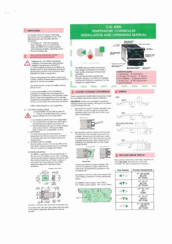
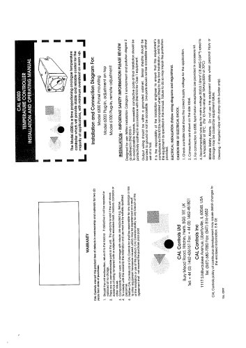
UNPACKING On receipt check for signs of damage and report any immediately to CAL. The following items are Included with the Instrument: . Accessory kit - 1 link for.changing Input voltage, push on connectors (only with 8300 and models supplied with standard socket). 2 jacking screws • Panel mounting clip CAL 8000 TEMPERATURE CONTROLLER INSTALLATION AND OPERATING MANUAL 2 INSTALLATION: IMPORTANT SAFETY INFORMATION PLEASE REVIEW A Designed for use: Within Installation Category II environment and pollution degree 2 as defined in EN61010-1: To avoid possible hazards accessible conductive parts of final installation should be protectively earthed in accordance with EN6I010 for Class 1 equipment. Output wiring should be within a grounded cabinet. Sensor sheaths should be bonded to ground or not be accessible. Live parts should not be accessible without use of a tool. CAL Contro The 8000 uses the latest production and design techniques to provide a high quality analogue temperature controller. The advanced time proporttonal circuitry will give accurate and reliable control with minimum overshoot for lire majority of applications CONTENTS GUIDE 1 Unpacking 2 Installation 3 Voltage Conversion 4 Wiring 5 Error Display 6 Manual Reset 7 Scale Lock 8 SP2 Adjustment 9 Specifications It is the responsibility of the installation engineer to ensure that this equipment's compliance to EN61010 is not impaired when fitted to the final Installation and to use this equipment as specified In this manual, failure to do so may impair the protection provided. Follow wiring diagrams and regulations. 2.1 ELECTRICAL INSTALLATION CAUTION RISK OF ELECTRICAL SHOCK A1. Check controller label Is the correct supply voltage for your application. 2 Connections are shown cn the side label. 3. For connection to socket use. 250 Faston receptacles provided In accessory kit. 4. Recommended wire size for mains voltage and outputs 32/0.2 1,0mm2 (18 AWG 0.04'g rated to 6 Amps/300V at 70°C. 5 IMPORTANT It ts recommended that interference suppressors are fitted across relay contacts to prolong relay life and reduce electrical Interference. 6 ULTIMATE SAFETY ALARMS Normal safely device: Do not use SP2 as the sole alarm where personal injury' or damage may be caused by equipment failure. 2.2PANEL MOUNTING The 8000 is mounted In the panel through a 45 x 45 mm (1/16 DIN) cut out. The mounting clip should be pushed against the panel until Ihe ratchel holds the unit (irmly In place. If necessary the mounting can be further lightened using the 2 jacking screws provided c*n»>niiOfrt »i ft*” (<rctx*i) Cloaning - ir reauired wipe wilh damp ctolh(waier only) To remove the unit from the panel press the legs of Ihe clips In opposite directions to release ratchet. 3 115/230V VOLTAGE CONVERSION These operational modificalions should be made by a qualified technician before installation IMPORTANT: Check your installation operating voltage belore proceeding. Wrongtul conversion could damage this unit. 1. Separate the output module assembly trom the main module by gently levering the retaining clips from both slots in the cover with a screwdriver Modulo Conor Remove the output module and then pull the PC8 from the module cover as far as possible. Unplug the potentiometer wiring by releasing the lock, fhe PCS can now be completely removed. TAKE CARE NOT TO DAMAGE OR DISTURB ANY OF THE OTHER COMPONENTS Annofluo PCB Ouicui Modulo Check side lobol for supply voltage. Tills con be changed by plug In links on the main pcb. (A spare link is provided In Ihe accessory kit) Use pliers to remove a link, and ensure that when fitting a new link It ts fully pushed Into place. For 230Vac mains supply - link 2 filled For 115Vac mains supply - link I and 3 fitted 5 PROCESS ERROR DISPLAY Has a 5 step Indication, each step operates for 2% of full scale. Example for a full scale of 0-300° Ihe LED's would be lit as shown:-
Open the catalog to page 1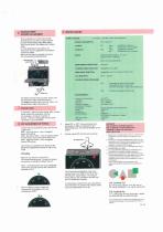
POWER CONSUMPTION: OUTPUTS: (Optional) INPUTS: SENSOR BREAK PROTECTION: COMMON MODE REJECTION: SERIES MODE REJECTION: CJC REJECTION: CONTROL MODES (STANDARD) ENVIRONMENTAL Ambiont Temperature: Humidity: Altitude: Pollution Degree: Installation Category: Mouldings: Safely: Protection: EMC Emissions: EMC Immunity: Weight: 2. Adjust SP1 to 190 - Process temperature will remain at 200" for a period of lime depending upon the thermal stability of the system 3. Quickly adjust SP2 until the LED operates As the process temperature may have cooled down from 200° by the lime that SP2 LED Is III, repeal...
Open the catalog to page 2All Cdautomation catalogs and technical brochures
 Multidrive 3PH
16 Pages
 ENG CD Vario General Catalog
7 Pages
 CD-AUTOMATION-REVO-CATALOG-2018
16 Pages
 6000 Series
6 Pages
 Revo Connect catalogue
20 Pages
 ST THE STARTER EVOLUTION
12 Pages


- Switching relay
- DIN rail converter
- Ethernet converter
- Compact converter
- Solid state relay
- Serial converter
- RS-232 converter
- RS-485 converter
- DC solid state relay
- Protocol converter
- AC solid state relay
- Communications converter
- Soft starter
- Motor soft starter
- Single-phase solid state relay
- Phase power controller
- RS422 converter
- Modbus RTU converter
- Modbus converter
- Thyristors power controller