Solenoid valves
1 /18Pages

Solenoid valves
1 /18Pages
Catalog excerpts

Solenoid valves
Open the catalog to page 1
32 cover; – chloroprene rubber (CR) for outlet seal gaskets; – P.T.F.E. for seat gaskets. INSTALLATION The valves can be installed in all sections of a refrigerating system, in compliance with the limits and capacities indicated in Tables 3 and 6. Tables 1 and 4 show the following functional characteristics of a solenoid valve: – PS; – TS; – Kv factor; – minimum Opening Pressure Differential (minOPD), that is the minimum pressure differential between inlet and outlet at which a solenoid valve, pilot operated, can open and stay opened; – maximum Opening Pressure Differential (MOPD according to...
Open the catalog to page 2
35 Connectors are not included in the boxes and have to be ordered separately.
Open the catalog to page 5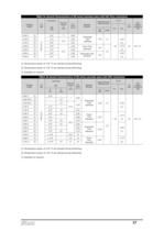
37 TABLE 4a: General Characteristics of NO valves (normally open) with SAE Flare connections Catalogue number 0,05 0,07 0,05 SAE Flare 3/8" 1/2" 5/8" 5/8" 3/4" 5/8" 3/4” 7 12,5 16,5 0,80 2,20 2,61 3,80 4,80 3,80 4,80 21 19 – 35 +105 (1) +110 (2) +105 (1) 32 Art. 3.3 Connections Seat size nominal Ø [mm] Kv Factor [m3/h] Operating Principles MOPD Opening Pressure Differential [bar] min OPD min. TS [°C] max. PS [bar] Risk Category according to PED Coil type HM3 (D.C.) 1164/3 1170/4 1170/5 1150/5 1150/6 1190/5 1190/6 R R R R R R R Diaphragm pilot operated Diaphragm Pilot Operated Piston Pilot Operated...
Open the catalog to page 7
40 Protection against electric contacts is class I for all the coils. Therefore, for safety purposes, coils must be effectively connected to an earthing system. Rubber gaskets on the upper and lower ends of coil ensure moisture protection of winding. Coils HM2 and HM3 may be joined to all connectors produced by Castel except type 9155/R01; protection degree guaranteed by this system, coil (HM2, HM3) + connector, is IP65 according to EN 60529. Coils HM4 must be preferably used with connector type 9155/R01; protection degree guaranteed by this other system, coil HM4 + connector 9155/R01, is IP65/IP68...
Open the catalog to page 10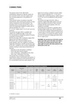
43 gland nut of casing is suitable to receive cables with an external diameter of 6 ÷ 9 mm and is provided with a self-locking device. Cables sized 3 x 0,75 mm2 are to be preferred for this junction box too. The junction box type 9155/R01 offers a protection degree IP65/IP68 against dust and water, according to EN 60529, when correctly installed with the proper gaskets, which are supplied as standard. The junction box 9150/R45 is equipped with a full-wave bridge rectifier plus VDR for protection. The VDR device, Voltage e-Dependent-Resistor, is a special type of resistor, placed in parallel to...
Open the catalog to page 13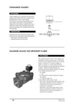
44 APPLICATIONS The solenoid valves, shown in this chapter, are classified “Pressure accessories” in the sense of the Pressure Equipment Directive 97/23/EC, Article 1, Section 2.1.4 and are subject of Article 3, Section 1.3 of the same Directive. They are designed for the applications specified in Table 1 where the different fluids are indicated with the following symbols, according to an already established code: – W = Water; – L = Air; – B = Secondary coolants (solutions of glycol and water); – O = Light oils (gas oil). In short these valves may be used: – with fluids in the gaseous state proper...
Open the catalog to page 14
45 OPERATION All the valves for different fluids are normally closed. NC = when the coil is de-energised the plunger stops the refrigerant flow. The valves series 1512 and 1522 are direct acting, while the valves series 1132 and 1142 are pilot operated with diaphragm. CONSTRUCTION The main parts of the valves are made with the following materials: – hot forged brass EN 12420 – CW 617N for body and cover; – austenitic stainless steel EN 10088-2 – 1.4303 for enclosure where the plunger moves; – ferritic stainless steel EN 10088-3 – 1.4105 for plunger; – austenitic stainless steel EN ISO 3506 –...
Open the catalog to page 15
46 AIR CAPACITY Table 2 provides the values of air capacity under the following conditions: • temperature at valve inlet = 20 °C; • discharge pressure (absolute) = 1 bar; • Kv of the valve under consideration = 1 m3/h. The pressures upstream the valve specified in the table are absolute values. EXAMPLE Select the valve suitable for use with approximately 200 m3/h of air, assuming an absolute pressure of 8 bars at valve inlet ( = 7 bars of relative pressure + 1 bar) and an acceptable pressure drop across the valve of 1,5 bars. In the column of pressures upstream the valve, the value 8 is shown;...
Open the catalog to page 16All CASTEL catalogs and technical brochures
 CASTEL - 2013 General Catalogue
105 Pages
 VALVES FOR REFRIGERATING SYSTEMS
34 Pages
 REFRIGERATING SYSTEMS PROTECTORS
38 Pages
 OIL CONTROL SYSTEM
22 Pages
 PRODUCTS FOR CO2 SYSTEMS
7 Pages
 Products catalogue
101 Pages


Archived catalogs
 Expansion valves
16 Pages
 Safety devices
16 Pages
 Check valves
6 Pages
 Water regulating valves
6 Pages
 Dehydrators and Filters
28 Pages
 Oil separators
6 Pages
 Valves
20 Pages
 Threaded brass fittings
10 Pages
 Products Catalogue 2008
84 Pages
