Safety devices

Safety devices
Valves series 3030 are safety devices as per the 97/23/EC Directive. These unbalanced, direct-loaded safety valves open when fluid pressure exceeds the spring's opposing force. They are identified by a model number that includes family identification and setting pressure.
The valve body is made from die-forged brass and includes components like the nozzle, disc guide, and setting spring holder. The disc is made from brass and PTFE for a good seal and to prevent sticking. The spring is made from DIN 17223-1 steel, ensuring valve reclosing after pressure relief.
These valves prevent pressure from exceeding the maximum allowable pressure (PS) of the equipment they protect. They are suitable for refrigerating systems, heat pumps, and simple pressure vessels, handling refrigerant fluids, air, and nitrogen.
Valves are marked with EC marking, manufacturer details, model, flow section, discharge coefficient, pressure, temperature range, set pressure, production date, and serial number.
According to the 97/23/EC Directive, pressure equipment likely to exceed permissible limits must have suitable protection devices. Selection should consider the system's specific standards and requirements.
Sizing involves calculating the minimum required discharge capacity based on system conditions. Installation should ensure minimal pressure loss and consider safety risks from discharged refrigerant.
An example calculation for a refrigerating system using refrigerant R407C is provided, detailing steps to determine the minimum required discharge capacity and the appropriate safety valve model.
The document provides a formula for calculating pressure loss in upstream and downstream lines, using parameters such as inlet and outlet pressure, flow area, and pressure loss coefficients. An example calculation is provided for a discharge pipe on a safety valve.
The 3060 series safety valves are unbalanced, direct-loaded devices that open when fluid pressure exceeds the spring force. Constructed from EN 12420-CW617N brass with a PTFE gasket, they protect against overpressure in systems like refrigerating components and simple pressure vessels.
The valves comply with the 97/23/EC Directive and EN 378-2:2008 Standard, with markings indicating manufacturer details, flow direction, pressure limits, and other specifications.
The document outlines requirements for selecting and sizing safety valves according to the 97/23/EC Directive and EN 378-2:2008 Standard, emphasizing the need for protection devices to prevent exceeding maximum allowable pressure.
Series 3033 and 3063 ball shut-off valves are designed for use with the same fluids as the safety valves, allowing for the removal of safety valves for maintenance without depressurizing the system.
Type 3032 changeover devices enable the use of dual pressure relief valves, allowing maintenance on one valve while the other remains operational.
The document discusses the use of fusible plugs as pressure relief devices, noting restrictions on their use with certain refrigerants and system sizes according to EN 378-2:2008 Standard.
Fusible plugs series 3080/.C and 3082/.C are safety devices under the 97/23/EC Directive, designed to relieve pressure by melting at a predetermined temperature. They are classified under Risk Category I.
The fusible plug consists of an NPT plug with a taper hole filled with a fusible alloy. Materials include brass for the plug and a cadmium and lead-free eutectic alloy for the fusible material.
Fusible plugs protect refrigerating systems or heat pumps from overpressure due to excessive external heat sources, compatible with Group 2 refrigerant fluids as per the 97/23/EC Directive.
According to EN 13136: 2001/A1:2005, fusible plugs must be sized based on critical flow conditions, involving parameters like minimum flow area, discharge capacity, pressure, and specific volume of gas or vapor.
The minimum required discharge capacity is determined by the heat flow rate, external surface area, and heat of vaporization. The derated coefficient of discharge (Kdr) varies based on the connection type.
The table provides specifications for fusible plugs 3080 and 3082, including connection sizes, flow diameters, flow sections, melting points, and torque requirements. All listed plugs fall under Risk Category I.
Catalog excerpts
Safety devices
Open the catalog to page 1
50 atmosphere. For this reason, during relief, a gas leak occurs through this orifice. Utilized material: EN 12420-CW617N brass. Disc: obtained through bar machining and equipped with gasket, it ensures the required sealing degree on the valve seat. The gasket is made in P.T.F.E. (Polytetrafluorethylene), a material that, during valve estimated service life, maintains a good strength and does not cause the disc to stick on the seat. The disc is properly guided in the body and the guide action can never fail; there are no glands or retaining rings that hamper the movement thereof. Utilized material:...
Open the catalog to page 2
51 L H1 H2 D H3 Ch safety devices such as safety valves. Such devices shall prevent pressure from permanently exceeding the max allowable pressure PS of the equipment they protect. In any case, a short pressure peak limited to 10% of admissible maximum pressure is permitted. As to the selection and sizing of the suitable protection device, users shall refer to the specific sector or product standards. EN 378-2: 2008 Standard “Refrigerating systems and heat pumps – safety and environmental requirements – Part 2: Design, construction, testing, marking and documentation”, harmonized with 97/23/EC...
Open the catalog to page 3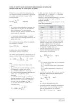
52 for this calculation the value of k shall be as measured at 25 °C. (Section 7.2.3, Standard EN 13136: 2001/A1:2005). Values of k and calculated values of C for some refrigerants are given in table A.1 of the aforesaid standard. Following we show the values of k and C for the more useful refrigerants. SIZING OF SAFETY VALVES DESIGNED TO DISCHARGE GAS OR VAPOUR AT CRITICAL FLOW (Ref. EN 13136: 2001/A1: 2005) Critical flow occurs when the backpressure pb (the pressure existing immediately at the outlet of a safety valve) is below or equal to the critical pressure: [bar abs] with: – po = actual...
Open the catalog to page 4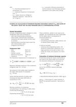
53 – çv = volumetric efficiency estimated at suction pressure and discharge pressure equivalent to the safety valve setting. with: – V = theoretical displacement of compressor [m3] – n = rotational frequency of compressor [min –1] – ñ10 = vapour density at refrigerant saturation pressure / dew point at 10 °C [kg/m3] These conditions, settled in any case by the designer, are considered the most unfavorable for the safety valve in consequence of functional defects as: – move mistake; – non-working of automatic safety devices, set to operate before safety valve. It shall be excluded: – closeness...
Open the catalog to page 5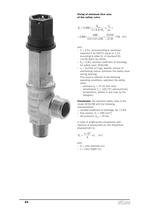
54 Sizing of minimum flow area of the safety valve [mm2] with: – C = 2,51, corresponding to isentropic exponent k for R407C equal to 1,14, according to table A1 of standard EN 13136:2001/A1:2005; – Kd = 0,83, certified coefficient of discharge for safety valve 3030/88; – vo = 0,0104 [m3/kg], specific volume of overheating vapour upstream the safety valve during relieving. This value is referred to the following operating conditions, upstream the safety valve: – pressure po = 27,25 [bar abs]; – temperature To = 100 [°C] (precautionary temperature, settled in any case by the designer). Conclusion:...
Open the catalog to page 6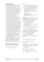
55 with: – A = flow area of safety valve [mm2]; – Ain = inside area of inlet tube to valve [mm2]; – Kdr = Kd x 0,9, derated coefficient of discharge; – C = function of isentropic coefficient k; – î = addition of pressure loss coefficients în of any component and piping; The coefficients în are relevant to: – pipe elements loss, as connections and bends; – valves loss; – loss along the pipe and are listed in EN 13136:2001/A1:2005 Standard, Table A.4. Example: assume to install, on the condenser of the previous example, a safety valve type 3030/88, set to 25 bar, using a steel union with the following...
Open the catalog to page 7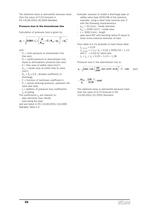
56 Example: assume to install a discharge pipe on safety valve type 3030/88 of the previous example, using a steel tube nominal size 2” with the following characteristics: - dout = 53 [mm] , inside diameter - Aout = 2206 [mm2] , inside area - L = 3000 [mm] , length - pipe bend 90° with bending radius R equal to three times external diameter of tube From table A.4 it’s possible to have these data: - î1 (bend) = 0,25 - î2 (length) = ë x L/ din = 0,02 î 3000/53 = 1,13 with ë = 0,02 for steel tube - îT = î1 + î2 = 0,25 + 1,13 = 1,38 Pressure loss in the downstream line is: The obtained value is admissible...
Open the catalog to page 8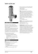
57 SAFETY VALVES 3060 GENERAL DESCRIPTION Valves series 3060 are safety devices according to the definition given in Article 1, Point 2.1.3, 2nd dash of 97/23/EC Directive and are the subject of Article 3, Point 1.4 of aforesaid Directive. The valves above mentioned are standard type, unbalanced, direct-loaded safety valves. Valve opening is produced by the thrust the fluid under pressure exerts on the disc, when said thrust exceeds, under setting conditions, the opposing force of the spring acting on the disc. Valves are identified by means of: – a model number formed of an alphanumerical coding...
Open the catalog to page 9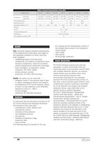
SCOPE Use: protection against possible overpressures of the apparatuses listed below, with regard to the operating conditions for which they have been designed: – refrigerating system and heat pump components, for instance: condensers, liquid receivers, evaporators, liquid accumulators, positive displacement compressor discharge, heat exchangers, oil separators, piping. (reference: EN 378-2: 2008); – simple pressure vessels (reference: 87/404/ EEC Directive). Fluids: the valves can be used with: • refrigerant fluids, in the physical state of gas or vapour, belonging to Group II according to the...
Open the catalog to page 10
59 Ch H1 L H2 H3 ØD for calculation” highlights the possible causes of overpressure in a system and makes available to users the instruments for pressure relief device sizing, among which the safety valves. For sizing and installation of safety valves series 3060 see the previous chapter of safety valves series 3030. TABLE 4: Dimensions and Weights of valves 3060 Catalogue number Weight [g] 3060 Ø D L Ch H1 H2 H3 21,5 21,5 21,5 21,5 24,5 30 30 35 35 35 35 39,0 40 40 20 20 20 20 23 27 27 33,5 33,5 33,5 33,5 37 37 40 46,5 46,5 46,5 46,5 52,5 59,5 59,5 80 80 80 80 89 96,5 99,5 180 195 195 195 240...
Open the catalog to page 11All CASTEL catalogs and technical brochures
 CASTEL - 2013 General Catalogue
105 Pages
 VALVES FOR REFRIGERATING SYSTEMS
34 Pages
 REFRIGERATING SYSTEMS PROTECTORS
38 Pages
 OIL CONTROL SYSTEM
22 Pages
 PRODUCTS FOR CO2 SYSTEMS
7 Pages
 Products catalogue
101 Pages


Archived catalogs
 Expansion valves
16 Pages
 Solenoid valves
18 Pages
 Check valves
6 Pages
 Water regulating valves
6 Pages
 Dehydrators and Filters
28 Pages
 Oil separators
6 Pages
 Valves
20 Pages
 Threaded brass fittings
10 Pages
 Products Catalogue 2008
84 Pages
