

OIL CONTROL SYSTEM

OIL CONTROL SYSTEM
Catalog excerpts
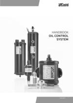
HANDBOOK OIL CONTROL SYSTEM www.castel.it 1 1
Open the catalog to page 2
INDEX Oil Control Systems Oil Separators Oil Reservoirs Oil Reservoir Pressure Valves Mechanical Oil Level Regulators Strainers Liquid Indicators 5 6 10 12 13 16 17 FROM QUALITY OUR NATURAL DEVELOPMENT After more than forty years in the industry of Refrigeration and Air Conditioning components, Castel Quality Range of Products is well known and highly appreciated all over the world. Quality is the main issue of our Company and it has a special priority, in every step, all along the production cycle. We produce on high tech machinery and updated automatic production lines, operating in conformity...
Open the catalog to page 4
EXTERNAL LEAKAGE All the products illustrated in this Handbook are submitted, one by one, to tightness tests besides to functional tests. Allowable external leakage, measurable during the test, agrees to the denition given in the Standard EN 12284: 2003, Par. 9.4: “During the test, no bubbles shall form over a period of at least one minute when the specimen is immersed in water with low surface tension, …”. PRESSURE CONTAINMENT All the products illustrated in this Handbook, if submitted to hydrostatic test, guarantee a pressure strength at least equal to 1,43 x PS in compliance with the Directive...
Open the catalog to page 5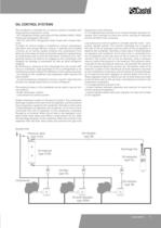
OIL CONTROL SYSTEMS is handbook is intended for oil control systems installed with reciprocating compressors using: - HFC refrigerants uids, particularly R134a, R404A, R407C, R507 mixed with polyolester lubricants - Old CFC and HCFC refrigerants uids mixed with mineral lubricants. A proper oil control system is essential to ensure compressors lubrication and energy ecient cooling. If selected and installed correctly, an oil control system protects the compressors from both low and excess oil levels and avoids expensive replacements of compressors due to incorrect lubrication. Excessive oil in...
Open the catalog to page 6
OIL SEPARATORS APPLICATIONS CONSTRUCTION The oil separators, shown in this handbook, are classified “Pressure vessels” in the sense of the Pressure Equipment Directive 94/23/EC, Article 1, Section 2.1.1 and are subject of Article 3, Section 1.1 of the same Directive. They are designed for installation on commercial refrigerating systems and on civil and industrial conditioning plants, which use refrigerant fluids proper to the Group II (as defined in Article 9, Section 2.2 of Directive 97/23/EC and referred to in Directive 67/548/EEC). The advantages of the oil separator on the discharge line...
Open the catalog to page 7
INSTALLATION The oil separators type 5520 and 5540 should be installed in the discharge line between the compressor and the condenser mounted securely in a vertical position and reasonably close to the compressor. To prevent the return of refrigerant from condenser, during the off cycle of the system, it’s advisable to install a check valve between the condenser and oil separator outlet connection. Oil separator performs best when operating at or near the compressor discharge temperature. In location the oil separator, choose a position to avoid, as far as possible, chilling of the shell, which...
Open the catalog to page 8
OIL RESERVOIRS APPLICATIONS INSTALLATION e oil reservoirs, shown in this handbook, are classied “Pressure vessels” in the sense of the Pressure Equipment Directive 94/23/ EC, Article 1, Section 2.1.1 and are subject of Article 3, Section 1.1 of the same Directive. ey are installed on commercial refrigerating systems and on civil and industrial conditioning plants, which use refrigerant uids proper to the Group II (as dened in Article 9, Section 2.2 of Directive 97/23/EC and referred to in Directive 67/548/EEC). ese reservoirs are used in “Low pressure oil control systems” and provide a holding...
Open the catalog to page 11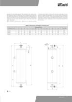
between the two sight glasses. is procedure may require several charges as the oil is adsorbed in the refrigerant and coats the low side tubing. When the refrigerating system is balanced the oil level in the reservoir must be controlled during every maintenance inspection and oil should be added again if level falls below the lower sight glass. When adding or replacing an oil reservoir to an existing system, it should only be lled to the top of the lower sight glass. As the system is placed into operation, the oil level should be observed during the rst two days. If the level decreases below...
Open the catalog to page 12
OIL RESERVOIR PRESSURE VALVES APPLICATIONS e reservoir pressure valves, shown in this handbook, are classied “Pressure accessories” in the sense of the Pressure Equipment Directive 94/23/EC, Article 1, Section 2.1.4 and are subject of Article 3, Section 1.3 of the same Directive. ese valves are designed for use in “Low pressure oil control systems” and are installed on commercial refrigerating systems and on civil and industrial conditioning plants, which use refrigerant uids proper to the Group II (as dened in Article 9, Section 2.2 of Directive 97/23/EC and referred to in Directive 67/548/EEC)....
Open the catalog to page 13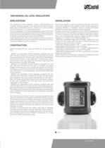
MECHANICAL OIL LEVEL REGULATORS APPLICATIONS INSTALLATION e mechanical oil level regulators, shown in this handbook, are classied “Pressure vessels” in the sense of the Pressure Equipment Directive 94/23/EC, Article 1, Section 2.1.1 and are subject of Article 3, Section 1.1 of the same Directive. ey are installed on commercial refrigerating systems and on civil and industrial conditioning plants, which use refrigerant uids proper to the Group II (as dened in Article 9, Section 2.2 of Directive 97/23/EC and referred to in Directive 67/548/EEC). ese regulators are used in “Low pressure oil control...
Open the catalog to page 14
TABELLA 7: General Characteristics of Oil Level Regulators Connections Catalogue Number Compressor Crankcase Oil level inspection Equalisation Flanged with 3 bolts dia 1.7/8" and 4 bolts dia 50 mm 5640/A 5640/B Oil inlet [SAE Flare] Regulation type Flanged with 3 bolts dia 1.7/8" and 4 bolts dia 50 mm 2 sight glasses already mounted 5640/C Oil pressure Volume differential (1) [l] [bar] Oil level position TS [°C] min. max. PS [bar] 1900 3/8" not adjustable no Fixed at 1/2 sight glass 0,35 / 2,1 0.8 – 10 + 130 32 1 sight glass already mounted 5640/D Risk Weight Category [g] according to PED 1950...
Open the catalog to page 15All CASTEL catalogs and technical brochures
 CASTEL - 2013 General Catalogue
105 Pages
 VALVES FOR REFRIGERATING SYSTEMS
34 Pages
 REFRIGERATING SYSTEMS PROTECTORS
38 Pages
 PRODUCTS FOR CO2 SYSTEMS
7 Pages
 Products catalogue
101 Pages


Archived catalogs
 Expansion valves
16 Pages
 Solenoid valves
18 Pages
 Safety devices
16 Pages
 Check valves
6 Pages
 Water regulating valves
6 Pages
 Dehydrators and Filters
28 Pages
 Oil separators
6 Pages
 Valves
20 Pages
 Threaded brass fittings
10 Pages
 Products Catalogue 2008
84 Pages
