

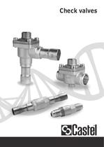
Check valves

1 / 6 PagesView full catalog
Check valves
Product catalog summary
Installation
The check valves can be installed in any section of a refrigerating system to prevent reverse flow, adhering to the limits and capacities specified in Table 3. Before installation, ensure the system is clean, as PTFE gaskets are sensitive to debris. The flow direction should match the arrow on the valve body. The valves can be installed in various positions depending on the type, with specific orientations recommended for each.
Applications
These check valves are classified as "Pressure accessories" under the Pressure Equipment Directive 97/23/EC. They are suitable for commercial refrigeration systems and civil and industrial conditioning plants using Group II refrigerant fluids. For high-temperature applications, such as near compressors, special gasket-equipped valves (types 3122, 3142, and 3182) are available.
Materials
The valves are constructed from hot forged brass for the body and cover, copper for solder connections, austenitic stainless steel for the spring, chloroprene rubber for outlet seals, and PTFE for seat gaskets.
Functional Characteristics
Table 1 outlines the functional characteristics of the check valves, including PS, TS, Kv factor, and minimum opening pressure differential. These parameters are crucial for ensuring the valve operates correctly under specified conditions.
Refrigerant Flow Capacity
Table 3 provides detailed refrigerant flow capacities for various valve models under specific operating conditions, including evaporating and condensing temperatures, and pressure drops. This information is essential for selecting the appropriate valve for a given application.
Dimensions and Weights
Table 2 lists the dimensions and weights of different valve models, which are important for installation planning and system design.
The check valves can be installed in any section of a refrigerating system to prevent reverse flow, adhering to the limits and capacities specified in Table 3. Before installation, ensure the system is clean, as PTFE gaskets are sensitive to debris. The flow direction should match the arrow on the valve body. The valves can be installed in various positions depending on the type, with specific orientations recommended for each.
Applications
These check valves are classified as "Pressure accessories" under the Pressure Equipment Directive 97/23/EC. They are suitable for commercial refrigeration systems and civil and industrial conditioning plants using Group II refrigerant fluids. For high-temperature applications, such as near compressors, special gasket-equipped valves (types 3122, 3142, and 3182) are available.
Materials
The valves are constructed from hot forged brass for the body and cover, copper for solder connections, austenitic stainless steel for the spring, chloroprene rubber for outlet seals, and PTFE for seat gaskets.
Functional Characteristics
Table 1 outlines the functional characteristics of the check valves, including PS, TS, Kv factor, and minimum opening pressure differential. These parameters are crucial for ensuring the valve operates correctly under specified conditions.
Refrigerant Flow Capacity
Table 3 provides detailed refrigerant flow capacities for various valve models under specific operating conditions, including evaporating and condensing temperatures, and pressure drops. This information is essential for selecting the appropriate valve for a given application.
Dimensions and Weights
Table 2 lists the dimensions and weights of different valve models, which are important for installation planning and system design.
See more
Catalog excerpts
Check valves
Open the catalog to page 1
66 INSTALLATION The valves can be installed in any section of a refrigerating system, where it is necessary to avoid an inversion of the refrigerating flow, in compliance with the limits and capacities indicated in table 3. Table 1 shows the following functional characteristics of a check valve: – PS; – TS; – Kv factor; – minimum opening pressure differential, that is the minimum pressure differential between inlet and outlet at which a check valve can open and stay opened. Before connecting the valve to the pipe it is advisable to make sure that the refrigerating system is clean. In fact the...
Open the catalog to page 2All CASTEL catalogs and technical brochures
 CASTEL - 2013 General Catalogue
105 Pages
 VALVES FOR REFRIGERATING SYSTEMS
34 Pages
 REFRIGERATING SYSTEMS PROTECTORS
38 Pages
 OIL CONTROL SYSTEM
22 Pages
 PRODUCTS FOR CO2 SYSTEMS
7 Pages
 Products catalogue
101 Pages


Archived catalogs
 Expansion valves
16 Pages
 Solenoid valves
18 Pages
 Safety devices
16 Pages
 Water regulating valves
6 Pages
 Dehydrators and Filters
28 Pages
 Oil separators
6 Pages
 Valves
20 Pages
 Threaded brass fittings
10 Pages
 Products Catalogue 2008
84 Pages

*Prices are pre-tax. They exclude delivery charges and customs duties and do not include additional charges for installation or activation options. Prices are indicative only and may vary by country, with changes to the cost of raw materials and exchange rates.
About DirectIndustry
DirectIndustry is a marketplace that offers B2B players a complete experience, from product sourcing to purchase. DirectIndustry is an entity of VirtualExpo Group.
Are you a buyer?
Are you a supplier?