
- Catalogs
- Carlyle Compressors
- 0 5 T / 0 6 T S C R E W COMPRESSOR A P P L I C AT I O N G U I D E

0 5 T / 0 6 T S C R E W COMPRESSOR A P P L I C AT I O N G U I D E

0 5 T / 0 6 T S C R E W COMPRESSOR A P P L I C AT I O N G U I D E
This document serves as a comprehensive guide for the application of Carlyle 06T semi-hermetic and 05T open drive twin screw compressors. It covers operational limits, necessary accessories, and guidelines to ensure warranty compliance. These compressors are suitable for commercial refrigeration, process cooling, environmental chambers, and air conditioning, offering benefits such as reduced vibration and minimized refrigerant leaks.
- Certification: UL and CSA approvals for specific refrigerants (R-22, R-134a, R-404A & R-507).
- Screw Compressor Size: Available in various displacement sizes with specific voltage requirements.
- Compressor Mounting: Rigid mounting is possible, but isolation mounts are recommended to reduce noise.
- Oil Type: Approved oils vary based on refrigerant application.
- Ambient Conditions: Designed for specific temperature ranges.
- Installation Environment: Suitable for machine rooms and external environments with enclosures.
- Pressure Relief Valve: Automatic reset high-pressure relief valve included.
- Discharge Check Valve: Prevents reverse refrigerant flow during off cycles.
- Compressor Inlet Screens: Field serviceable screens at all entry points.
- Service Valves: Standard and barstock service valves for different compressor models.
- Condenser Pressure Control: Essential for maintaining oil separation and preventing nuisance tripping.
- Operational Envelopes: Defines allowable operating pressure ranges for different refrigerants.
- Vapor Temperature Limits: Specifies operational limits for vapor temperatures.
- Minimum Oil Pressure Differential: Requires a minimum differential of 45 psi.
- Operating Speed Ranges: Details speed ranges for different compressor models.
Includes components like oil separators, piping configurations, and oil cooling systems.
Focuses on suction and interstage piping.
Details thermal protection, motor protection, and circuit breaker tables.
Includes information on the Carlyle Electronic Module and temperature control mechanisms.
Guidelines for subcooler selection and performance adjustments.
Provides general information, dimensions, and performance factors.
Includes oil charging, control circuit testing, and pre-start-up checklist.
Lists part numbers for accessories.
Appendix A and B provide details on electronic modules.
The document provides technical specifications and operational guidelines for Carlyle screw compressors, focusing on their compatibility with inverter drives, variable speed limits, mechanical unloading, and oil management systems.
The document provides technical specifications and installation instructions for the Carlyle LonCEM electronic module used in 74mm screw compressors. It covers both semi-hermetic (06T) and open-drive (05T) compressors, offering thermal protection by monitoring motor and discharge temperatures and providing liquid injection cooling as needed. The module also includes oil pressure protection and features such as reverse rotation protection and startup sequencing of solenoid valves.
The document details the motor requirements for different compressor models, specifying the necessary RPM and motor type. It emphasizes the need for high start torque motors, especially for low-temperature applications, and provides performance data based on specific conditions.
Instructions include mounting the module, connecting sensor inputs, and ensuring proper wiring of control outputs. Special instructions for 05T installations are highlighted, including the use of a 5K resistor as a jumper.
The document discusses the variable speed technology of screw compressors and provides speed limits for different models. It warns against overspeeding and outlines the impact on brake horsepower requirements.
A comprehensive checklist is provided for pre-start-up, including opening service valves, checking pressure switches, and verifying the direction of compressor rotation. The procedure also includes testing the control circuit and ensuring proper oil pressure.
Part numbers for various accessories, such as oil separators, solenoid valves, and circuit breakers, are listed for both single and multiple compressor systems.
The appendices include a functional overview, wiring schematic, and troubleshooting notes, providing additional details on module functions and installation requirements.
The document discusses the new LonCEM module for compressor control, which includes inputs for suction pressure, discharge pressure, oil pressure, motor temperature, and discharge temperature. It is part of a package with necessary sensors, wiring harnesses, and fittings. The document compares the old and new modules, provides a bill of materials, installation instructions, troubleshooting notes, and sensor input descriptions.
The new LonCEM replaces the older CEM model and incorporates three pressure transducers, eliminating the need for several electro-mechanical pressure switches. The document lists components no longer required with the new module.
The document provides a detailed bill of materials for packages with and without LonWorks communication. It includes part numbers and descriptions for each component.
Instructions cover mounting the module, installing sensor inputs, and control outputs. It emphasizes using shielded cables for sensor inputs to protect against electrical noise.
The module should be mounted in a protective environment with specific wiring instructions for sensor inputs and control outputs.
Details on installing suction and discharge pressure transducers, oil pressure connections, and temperature sensors are provided. The document specifies torque requirements and installation techniques.
The module controls various outputs such as compressor contactor, part-wind contactor, liquid injection for motor cooling and discharge temperature, unloader coil, oil and economizer solenoid, and VI coil. Each output's function and control logic are explained.
Differences in module application between 05T and 06T compressors are highlighted, including the use of a resistor for motor temperature input on 05T compressors.
Modules with LonWorks communication allow additional control functions and access to sensor input values over a control network. The document references additional resources for detailed network variable information.
The module allows polling of various sensor inputs over the network, including suction pressure, discharge pressure, oil pressure, motor temperature, and discharge temperature. The module's permanent memory stores sensor readings prior to the last compressor alarm, the number of compressor cycles, compressor run-time, and cumulative alarm trips for each compressor alarm.
Electrical Noise: Electrical noise can affect module operation. Sensor input wires should not run adjacent to high voltage wiring to prevent electromagnetic and capacitive coupling. Installations using variable frequency drives require special attention to avoid coupling with inverter power wiring.
Pressure Transducer Readings: Avoid adding a schraeder fitting to pressure transducer fittings. If used, ensure it is fully engaged to prevent false readings.
Service LED Lamp: The red LED indicates network installation status and module software functionality. A steady light suggests a hardware problem requiring module replacement.
Start-Up Sequence: Includes a 20-second delay between compressor starts, checks for reverse rotation, and monitors oil system pressure drop.
Motor Cooling Control: The motor cooling valve is activated based on motor temperature thresholds to prevent overheating.
Input Device Failures: The module shuts off the compressor if it detects input device failures.
Discharge Temperature Control: The motor cooling valve is controlled based on discharge temperature thresholds.
Oil Pressure Differential Protection: The compressor shuts off if the oil pressure differential drops below 45 psi for 90 seconds.
Oil System Pressure Drop Safety: Alarms and shutdowns are triggered based on specific pressure differential thresholds.
VI Control: The VI coil is controlled based on pressure ratio thresholds.
Proper grounding and use of shielded cables are essential to avoid electrical noise. Sensor wires should be grounded at the module end only.
Various alarms are triggered based on conditions such as reverse rotation, safety circuit open, oil system pressure drop, and temperature thresholds. Each alarm has a specific code and reset procedure.
Graphs and tables provide conversion data for pressure transducers and thermistors, translating sensor outputs to engineering units like PSI and temperature.
Catalog excerpts

Section 4 — Refrigerant Management System 4.1 Section 6 — Motor and Discharge Temperature Control 6.1 6.2 6.3 Section 7 — Subcooler Selection and Performance Data Adjustment 7.1 7.2 7.3 7.4
Open the catalog to page 2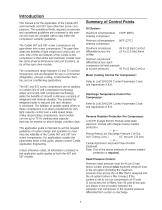
Introduction This manual is for the application of the Carlyle 06T semi-hermetic and 05T open drive twin screw compressors. The operational limits, required accessories and operational guidelines are contained in this manual and must be complied with to stay within the compressor warranty guidelines. The Carlyle 06T and 05T screw compressors are gear-driven twin screw compressors. The gear drive yields the benefits of light weight and small cubic volume. One of the key features of the Carlyle screw compressor is that all the semi-hermetic models have the same physical dimensions and port locations,...
Open the catalog to page 3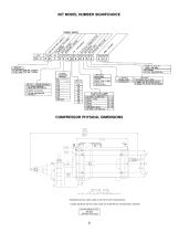
BOTTOM VIEW OPTION 2: C4) 011.1mm H0LE5 CFOR HARD MOUNTING ONLYD.
Open the catalog to page 4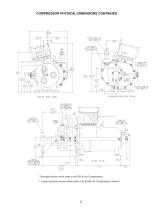
COMPRESSOR PHYSICAL DIMENSIONS CONTINUED ** * * Standard service valve used on all 33-54 cfm Compressors; ** Larger barstock service valve used on all 65-88 cfm Compressors (shown).
Open the catalog to page 5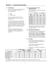
Section 1 — General Information 1.1 Certification 1.2 Screw Compressor Size (Displacement) UL and CSA approvals have been obtained on the 06T screw compressors with the following refrigerants: 06T compressors are available in the following displacement sizes: 1. R-22 2. R-134a 3. R-404A & R-507 The UL file number is SA4936. CSA file number is LR29937; CSA report number is LR29937-579c. For UL and CSA approvals it is essential that only listed special purpose circuit breakers or Furnas 958 series soild state overload relays be used. (See Section 5.2 and 5.3 for selection tables). The must trip...
Open the catalog to page 6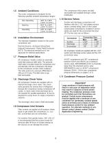
1.5 Ambient Conditions The screw compressor is designed for the following specified ambient temperature ranges: Non-Operating Start-Up Operating The compressor inlet screens are field serviceable and available through Carlyle distribution. Suction and discharge connections will interface with the 2-1/2" bolt pattern service valves currently being used on the Carlyle reciprocating compressors. Rotalock® service valves are used for the economizer line shut off. The line sizes are as follows: The intended installation modes for the screw compressor are: Suction Discharge Economizer Machine Rooms—Enclosed...
Open the catalog to page 7
Section 2 — Operating Specifications approval from Carlyle Application Engineering or warranty is voided. Oil cooling can be achieved through the use of an oil cooler or with desuperheating valves (as described in Oil Cooling Systems, Section 3.7) 2.1 Operational Envelopes The following operational envelopes, based on 65°F (18°C) return gas, show the allowable operating suction and discharge pressure ranges for R-134a, R-22, and R-507/R-404A. Operation outside of these envelopes requires Saturated Discharge Temperature deg F (deg C) Saturated Suction Temperature deg F (deg C) R-134a APPLICATIONS...
Open the catalog to page 8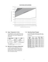
Saturated Discharge Temperature deg F (deg C) Saturated Suction Temperature deg F (deg C) 2.2 Vapor Temperature Limits 2.4 Operating Speed Ranges Any application of screw compressors must operate within the limits defined by the application maps for the various refrigerants and applications. Vapor Temp. Suction Economizer The operating speed range for the screw compressor is as follows for the different size range compressors. Model No. 06T**033 06T**039 06T**044 06T**048 06T**054 06T**065 06T**078 06T**088 06T**108 *SH = Superheat **The maximum economizer pressure allowable is 175.3 psig (13.1...
Open the catalog to page 9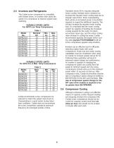
2.5 Inverters and Refrigerants The Carlyle screw compressor is compatible with inverter drives. An inverter drive varies the speed of a compressor to improve system load matching. VARIABLE SPEED LIMITS For 06TR Low Temp Compressors Model No. 06TRC033 06TRD039 06TRD044 06TRE048 06TRE054 06TRF065 06TRG078 06TRH088 06TRK108 Inverters are an effective tool for efficiently matching system loads with screw compressors. Motor size and motor cooling capabilities must be considered when using an inverter to increase speeds above 60 Hz. Following these guidelines will result in improved system design and...
Open the catalog to page 10
2.8 High Discharge Pressure Control All Carlyle screw compressors are equipped with one step of mechanical unloading.The unloader valve is controlled by a solenoid mounted on the compressor body. The compressor is unloaded when the solenoid is de-energized and loaded when the solenoid is energized. The compressor should always be started unloaded (for a minimum time determined by the control module) which will provide a soft start by partially relieving the compression chamber back to suction. Unloaded operation reduces the effective capacity by 30% to 62%, depending on the model and system condition...
Open the catalog to page 11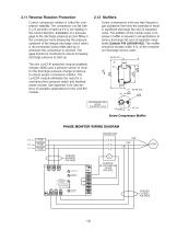
2.11 Reverse Rotation Protection Correct compressor rotation is critical for compressor reliability. The compressor can fail within 2-6 seconds of start-up if it is not rotating in the correct direction. Installation of a pressure gage at the discharge pressure access fitting in the compressor body (measuring the pressure upstream of the integral discharge check valve) is recommended during initial start-up or whenever the compressor is serviced. The gage should be monitored to ensure increasing discharge pressure at start-up. Screw compressors emit very high frequency gas pulsations that have...
Open the catalog to page 12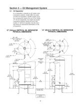
Section 3 — Oil Management System 3.1 Oil Separator An oil separator is required on all Carlyle screw compressor systems. Carlyle offers two sizes of vertical oil separators. Parallel systems (over two compressors) require the use of the Carlyle 14" (35.6cm) separator, and single and double compressor systems require the use of the Carlyle 12" (30.5cm) separator. See the drawings below for dimensional information on the oil separators. 14" (35.6cm) VERTICAL OIL SEPARATOR PHYSICAL DIMENSIONS 12" (30.5cm) VERTICAL OIL SEPARATOR PHYSICAL DIMENSIONS FOR REFERENCE ONLY INCHES [CENTIMETERS (cm)]
Open the catalog to page 13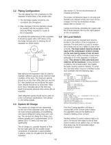
See section 9.1 for the recommended oil charging procedure. 3.2 Piping Configuration The inlet piping from the compressor to the separator should follow a few simple rules: The screw compressors have no oil sump and therefore are shipped empty and must not be charged. For the recommended oil type, please refer to Section 1.4. 1. The discharge header should be one consistent size throughout. 2. Step changes in the line diameter should be avoided with the exception of the reducing fittings required to couple to the oil separator. Carlyle recommends operating the system with the oil level between...
Open the catalog to page 14All Carlyle Compressors catalogs and technical brochures
 06T Performance DATA
101 Pages
 05 T Performance DATA
101 Pages
 Poster
1 Page
 trouble shooting
2 Pages
 5F/H Open-Drive Compressors
4 Pages
 Paragon Compressors
8 Pages


- Air compressor
- Stationary compressor
- Positive-displacement compressor
- Industrial compressor
- Reciprocating piston compressor
- Lubricated compressor
- Mobile compressor
- High-efficiency compressor
- Oil-lubricated compressor
- Portable compressor
- Refrigeration compressor
- Variable-speed compressor
- Industrial refrigeration refrigeration compressor
- Semi-hermetic refrigeration compressor
- Single-stage refrigeration compressor
- Piston refrigeration compressor
- Motorless compressor
- Screw refrigeration compressor
- Commercial refrigeration refrigeration compressor