
- Catalogs
- CARLO GAVAZZI
- Inductive Proximity Sensors EI1202TBCFL-3

Inductive Proximity Sensors EI1202TBCFL-3

Inductive Proximity Sensors EI1202TBCFL-3
- Housing Diameter: M12, M18, M30
- Sensing Distance: 2 to 15 mm
- Rated Operational Voltage: 20 to 250 VAC
- Output Type: SCR, make or break switching
- LED Indication: Yellow LED for output ON
- Connection Types: Plug versions M12 or 1/2" UNF
- Operational Current: Continuous ≤ 500 mA, Short-time ≤ 2.5 A
- Protection: Transient voltage 2.5 kV/0.5 J/500 Ω
- Operating Temperature: -25 to +70°C
- Degree of Protection: IP 67
- Approvals: UL (M18 and M30 types), CE-marking
- Ensure cable strain relief and protect the sensing face.
- Avoid interference from inductive voltage/current peaks by separating power cables.
- Do not use the proximity switch as a mechanical stop.
- Avoid repetitive flexing of the cable.
Catalog excerpts

?Stainless steel housing, cylindrical?Diameter: M12, M18, M30 ?Short versions?Sensing distance: 2 to 15 mm ?Rated operational voltage: 20 to 250 VAC ?Output: SCR, make or break switching?LED-indication for output ON ?Plug versions M12 or 1/2" UNF > TypeHousing diameter (mm)Rated operating dist. (mm)Output type Housing material Connection type > Proximity switch in stainless steel housings ranging from 12 to 30 mm. SCR, 500 mAoutput. Normally open orclosed output types. Plug ver-sions M12 or 1/2" UNF. > HousingRatedOrdering no.Ordering no.diameteroperatingSCR outputSCR outputdist. (S > n )Make switchingBreak switching M122 mm > 1) EI 1202 TBOFL-3EI 1202 TBCFL-3 M124 mm > 2) EI 1204 TBOFL-3EI 1204 TBCFL-3 M185 mm > 1) EI 1805 TBOFS-3EI 1805 TBCFS-3 M188 mm > 2) EI 1808 TBOFS-3EI 1808 TBCFS-3 M3010 mm > 1) EI 3010 TBOFS-3EI 3010 TBCFS-3 M3015 mm > 2) EI 3015 TBOFS-3EI 3015 TBCFS-3 > 1) For flush mounting in metal 2) For non-flush mounting in metal Rated operational volt. (U > e )24 to 240 VAC, 45 to 65 Hz Assured operating dist. (S > a )0 ≤ S > a ≤ 0.81 S > n (U > B )20 to 250 VAC, 45 to 65 Hz Repeat accuracy (R) ≤ 5% Rated operational current (Ie)Continuous Hysteresis (H) ≤ 500 mA Short-time ≤ 2.5 A, max. 20 ms (Differential travel) 3 to 20% of sensing distance Min. operational current (I Drift of sensing distance > m )5 mA due to temperature variation ≤ 10% Min. rated operational current (I > e ) 10 mA Ambient temperature OFF-state current (Ir) ≤ 2 mA at 250 VAC, typ. 1.2mA Operating -25 to +70C (-13 to +158аF) Storage -30 to +80C (-22 to +176аF) typ. 0.8 mA @ 120 V Degree of protection IP 67 Voltage drop (U > d ) ≤ 8 VAC, typ. 5 V (Nema 1, 2, 3, 4, 4x, 12, 13) Protection Transient Housing material Transient voltage 2.5 kV/0.5 J/500 Ω BodyStainless steel (1.4301) FrontBlue polyester, oil proof Power ON delay (t > v ) ≤ 100 ms, typ. 50 ms BackBlack polyester, oil proof Frequency of operating cycles (f)5 Hz Approvals UL (only M18 and M30 types) Indication for output ON LED, yellow CE-marking Yes > Specifications are subject to change without notice (07.12.01)
Open the catalog to page 1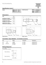
Specifications are subject to change without notice (07.12.01) size="-1">
Open the catalog to page 2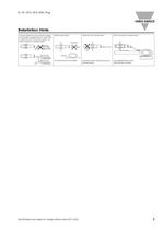
Relief of cable strainProtection of the sensing face Switch mounted on mobile carrierTo avoid interference from inductive voltage/current peaks, separate the prox. switch pow- er cables from any other power cables, e.g. motor, contactor or solenoid cables IncorrectCorrectThe cable should not be pulledA proximity switch should not serve asmechanical stopAny repetitive flexing of thecable should be avoided >
Open the catalog to page 3All CARLO GAVAZZI catalogs and technical brochures
 SCTL55 - Smart configurator
6 Pages
 Inductive sensors
8 Pages
 Fieldbuses
6 Pages
 Proximity Sensors Inductive
2 Pages
 BSQ-PIR360
2 Pages
 ECH40075
2 Pages
 DCT86A12300
3 Pages
 CGESHTWVT04
2 Pages
 Power Supplies SPD121201FP
3 Pages
 Safety Modules ND12D
2 Pages
 Timers AAM C D23
6 Pages
 Ultrasonic UA18CLD05NPM1TR
5 Pages




- Temperature probe
- Transformer
- Dry transformer
- Switching relay
- Digital indicator
- Communication gateway
- Current transformer
- Photoelectric sensor
- Fieldbus gateway
- Encapsulated transformer
- Electromechanical relay
- Leak monitor
- DIN rail electric energy meter
- Industrial transformer
- Time relay
- DIN rail gateway
- IoT gateway
- Variable frequency drive
- Light barrier
- Single-phase electric energy meter