- Catalogs
- Carling Technologies
- V-Series CONTURA SWITCHES
V-Series CONTURA SWITCHES
1 /14Pages

V-Series CONTURA SWITCHES
1 /14Pages
Catalog excerpts
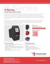
V-Series V-Series CONTURA SWITCHES The V-Series Contura II & III snap-in rocker switches offer countless unique options including choices for ratings, circuits, colors, illuminations and symbols. These single or double pole switches feature removable actuators in a choice of actuator styles and colors, and can be illuminated with either square or bar shaped lenses. Actuators may be purchased and stocked separately. An optional plug-in terminal connector enables pre-wiring of wire harnesses. The Contura switches with sealed option, are certified to IP66/68, signifying complete protection against dust and prolonged spray and submersion under pressure, and are recognized to UL1500 - Ignition Protection for Marine Products. These switches are vibration, shock, thermoshock, moisture and salt spray resistant. Temperature ratings range from -40°C to +85°C. Resources: Configure a Complete Part Download CAD & Sales Drawing Watch Product Video Product Highlights: • Countless options for ratings, circuits, colors, illuminations and legends • Sealed to IP66/68 for Above-Panel Components • Vibration, shock, thermoshock, moisture and salt spray resistant • Temperature range from -40°C to +85°C. Typical Applications: • On/Off Highway Equipment • Marine • Military Armored Vehicles • Mining Machinery and Equipment • Any application requiring environmental protection 60 Johnson Avenue, Plainville, CT 06062 Email: [email protected] Application Support: [email protected] Phone: 860.793.9281 Fax: 860.793.9231
Open the catalog to page 1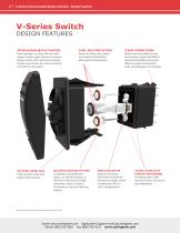
2 | V-Series Contura Sealed Rocker Switches - Design Features V-Series Switch DESIGN FEATURES INTERCHANGEABLE ACTUATORS Panel redesign is a snap with our wide range of rocker styles. Achieve maximum design variety with minimum inventory. Simply swap rockers to create an entirely new look for your panel. OPTIONAL PANEL SEAL Helps prevent water/dust ingress behind panel. DUAL SEAL PROTECTION Seals out water, dust, debris, and sealed to IP66/68 for above-panel components MULTIPLE LIGHTING OPTIONS In addition to Incandescent lamps, our LED illumination is offered in a wide array of light intensities,...
Open the catalog to page 2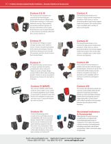
3 | V-Series Contura Sealed Rocker Switches - Actuator Options & Accessories Illuminated Indicators & Accessories The Contura II & III actuators are constructed of thermoplastic polycarbonate and are offered with a hard nylon overlay or a “soft-touch” elastomer overlay. These models incorporate aesthetic designs on the top and bottom of the rocker featuring two rows of raised “bumps” on the Contura II and three “indented” lines on the Contura III. The Contura IV’s “Shape to create a Shape” actuator works with the curves, contours & advanced styling of the latest panel designs, flowing with these...
Open the catalog to page 3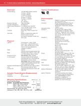
4 | V–Series Contura Sealed Rocker Switches - General Specifications Contact Rating .4VA @ 24VDC (MAX) resistive 15 amps, 125VAC 10 amps, 250VAC 1/2 HP 125-250VAC 20 amps, 4-14VDC 15 amps, 15-28VDC 10A, 14VT 6A, 125VAC L Dielectric Strength 1500 Volts RMS Insulation Resistance 50 Megohms Initial Contact Resistance 10 milliohms max. @ 4VDC Life Up to 100,000 cycles, circuit and load dependent Contacts Silver alloy, silver tin-oxide, fine silver Terminals Brass or copper/silver plate 1/4” (6.3mm) Quick Connect terminations standard. Solder lug, Wire Lead Lighted Incandescent - rated 10,000 hours...
Open the catalog to page 4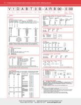
5 | V-Series Contura Sealed Rocker Switches- Contura II & III - Ordering Scheme 4 5 6 Termination Illumination Lamp 1 SERIES V 2 CIRCUIT Terminal Connections as viewed ( ) - momentary from bottom of switch: SP - single pole - uses terminals 1, 2 & 3. 8 terminal 0 terminal DP - double pole uses terminals 1, 2, 3, 4, 5 & 6. 1 8 - - 7 8 - - 7 Terminals 7, 8, 9 & 10 for lamp circuit only. 1 - - 4 1 - - 4 2 - - 5 2 - - 5 3 - - 6 3 - - 6 10 - - 9 Position: 1 2 3 SP DP 2 & 3, 5 & 6 Connected Terminals 1 & 2, 4 & 5 1 A ON NONE OFF 2 B (ON) NONE OFF 3 C ON NONE (OFF) 4 D ON NONE ON 5 F ON NONE (ON) 6...
Open the catalog to page 5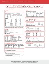
6 | V-Series Contura Sealed Rocker Switches - Contura II & III Locking - Ordering Scheme 4 5 6 Termination Illumination Lock 1 SERIES V 2 CIRCUIT Terminal Connections as viewed ( ) - momentary from bottom of switch: SP - single pole - uses terminals 1, 2 & 3. 8 terminal 0 terminal DP - double pole uses terminals 1, 2, 3, 4, 5 & 6. 1 8 - - 7 8 - - 7 Terminals 7, 8, 9 & 10 for lamp circuit only. 1 - - 4 1 - - 4 2 - - 5 2 - - 5 3 - - 6 3 - - 6 10 - - 9 Position: 1 2 3 SP DP 2 & 3, 5 & 6 Connected Terminals 1 & 2, 4 & 5 1 A ON NONE OFF 4 D ON NONE ON 6 J ON OFF ON 7 K ON OFF (ON) 8 L (ON) OFF (ON)...
Open the catalog to page 6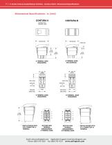
7 | V–Series Contura Sealed Rocker Switches - Contura II & III - Dimensional Specifications Email: [email protected] Application Support: [email protected] Phone: (860) 793–9281 Fax: (860) 793–9231 www.carlingtec
Open the catalog to page 7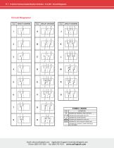
8 | V-Series Contura Sealed Rocker Switches - II to XIV - Circuit Diagrams Circuit Diagrams: CIRCUIT CODE CIRCUIT DIAGRAM CIRCUIT CODE CIRCUIT DIAGRAM DEFINITION DESIGNATES TERMINALS AND CONTACTS DESIGNATES MAINTAINED CIRCUITS DESIGNATES OTHER POSITION SYMBOL LEGEND CIRCUIT CODE DESIGNATES MOMENTARY CIRCUITS DESIGNATES TWO POSITION CONNECTION DESIGNATES EXTERNAL JUMPER PROVIDED BY CUSTOMER Email: [email protected] Application Support: [email protected] Phone: (860) 793–9281 Fax: (860) 793–9231 www.carlingtech.co
Open the catalog to page 8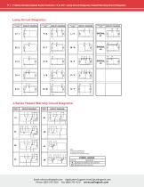
9 | V-Series Contura Sealed Rocker Switches - II to XIV - Lamp Circuit Diagrams, Hazard Warning Circuit Diagrams Lamp Circuit Diagrams: LAMP CIRCUIT CODE CIRCUIT DIAGRAM LAMP CIRCUIT CODE LAMP CIRCUIT CODE J-Series Hazard Warning Circuit Diagrams: CIRCUIT CODE CIRCUIT CODE CIRCUIT DIAGRAM CIRCUIT DIAGRAM LAMP CIRCUIT CODE CIRCUIT DIAGRAM NOTE: J circuits are available for all non-locking V-Series styles. Consult factory for partnumber details. DEFINITION DESIGNATES TERMINALS AND CONTACTS DESIGNATES LAMP LOCATION Email: [email protected] Application Support: [email protected] Phone: (860)...
Open the catalog to page 9All Carling Technologies catalogs and technical brochures
 641-Series
6 Pages
 Military Catalog
174 Pages
 Marine Catalog
190 Pages
 L-Series Circuit Breaker
8 Pages
 H-Series
14 Pages
 D-Series Circuit Breaker
10 Pages
 CX-Series Circuit Breaker
12 Pages
 Carling CB Catalog
202 Pages
 C-Series Circuit Breaker
26 Pages
 B-Series Circuit Breaker
20 Pages
 A-Series Circuit Breaker
28 Pages
 Carling GFCI
29 Pages
 On-Off Highway Industry
4 Pages
 Military Industry
4 Pages
 V-Series-Contura-X-XI-XII
14 Pages
 V-Series-Contura-XIV
14 Pages
 VP-Series
6 Pages
 W-Series
10 Pages
 700-800-Series
4 Pages
 R135-Series
2 Pages
 V-Series-Rotary
10 Pages
 110-216-Series
4 Pages
 ST-Series
8 Pages
 C-Series
4 Pages
 D-Series
4 Pages
 DK-EK-Series
4 Pages
 F-Series
4 Pages
 G-Series
4 Pages
 H-I-Series
4 Pages
 LT-Series
4 Pages
 MAAOA-215-Series
4 Pages
 BD-Series
10 Pages
 Carling Thermal CB
20 Pages
 TB-Series
6 Pages
 PB-Series
12 Pages
 PC-Series
14 Pages
 V-Charger
6 Pages
 ROCKER SWITCHES
176 Pages
 On-Off Highway Catalog
114 Pages
 Telecom-Datacom Industry
4 Pages
 Renewable Energy
64 Pages
 Renewable Energy Industry
4 Pages
 Medical Equipment Brochure
4 Pages
 On/Off Highway Brochure
4 Pages
 Renewable Energy Brochure
4 Pages
 Marine Brochure
4 Pages
 Telecom/Datacom Brochure
4 Pages
 Military Brochure
4 Pages
 Switches & Controls
172 Pages
 Miniature Switches
84 Pages
 Thermal Circuit Protection
18 Pages
 GFCI/ELCI Circuit Protection
28 Pages


- Single-pole switch
- Push-button switch
- Isolator switch
- Technology switch
- Circuit breaker
- Multipole switch
- Electromechanical switch
- Rotary electric switch
- IP67 switch
- Low-voltage main switch
- Touch push-button switch
- Plastic switch
- Action push-button switch
- Form push-button switch
- Metal switch
- Bipolar switch
- Hermetic switch
- Current circuit breaker
- Momentary push-button switch