- Catalogs
- Carling Technologies
- H-Series
H-Series
1 /14Pages

H-Series
1 /14Pages
Catalog excerpts
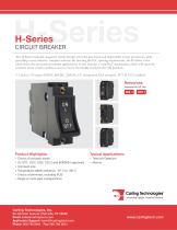
H-SeriesCIRCUIT BREAKER The H-Series hydraulic-magnetic circuit breaker provides maximum and dependable circuit protection, while providing a cost effective, compact solution. By meeting the IEC spacing requirements, the H-Series is the ideal choice for international market applications. It also features a “trip-free” mechanism, which will open the contacts when a fault condition occurs, even if the handle is held in the ON position. 1-3 poles; 1-35 amps; 65VDC, 80VDC, 250VAC; UL recognized, CSA accepted, TUV & CCC certified. Resources: Download 3D CAD Files Typical Applications: ♦ Telecom/Datacom ♦ Marine Product Highlights: ♦ Choice of actuator styles ♦ UL1077, CCC, CSA, C22.2 and EN60934 approvals ♦ Compact size ♦ Temperature stable operation -40° C to +80° C ♦ Choice of terminals, including PCB ♦ Single or multi-pole configurations Carling Technologies, Inc. 60 Johnson Avenue, Plainville, CT 06062 Email: [email protected] Application Support: [email protected] Phone: 860.793.9281 Fax: 860.793.9231
Open the catalog to page 1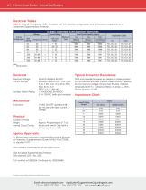
2 | H-Series Circuit Breaker - General Specifications Electrical Tables Table A: Lists UL Recognized, CSA Accepted and TUV Certified configurations and performance capabilities as a Component Supplementary Protector. Typical Protector Resistance Maximum Voltage Current Ratings Auxiliary Switch Rating DCR and Impedance values are based on measurements by the voltmeter ammeter method. Rated current is applied for one hour at a voltage not less than 20 volts. Ambient temperature: 25 °C; Tolerance: Below 10 amps +/- 25%; Above 10 amps +/-35% Impedance Chart Current Rating (Amps) Mechanical Endurance...
Open the catalog to page 2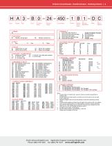
H-Series Circuit Breaker - Handle Actuator - Ordering Scheme | 3 Series Actuator Poles Circuit Aux/Alarm Actuator Mounting Color & Bezel/Barrier 2 ACTUATOR 1 A Handle, one per pole B Handle, one per unit 8 TERMINAL 6 1 Push ON 0.250 Tab (Q.C.) 2 Screw 8-32 with upturned lugs A Screw M4 with upturned lugs Printed Circuitboard Terminals L 90 Facing Left S Straight T Straight, Long 4 CIRCUIT A Switch Only (no coil) C 4 Series Trip (voltage) B Series Trip (current) G 4 Relay Trip (voltage) 5 AUXILIARY / ALARM SWITCH 0 without Aux Switch 3 3...
Open the catalog to page 3
4 | H-Series Circuit Breaker - Curved Rocker Actuator - Ordering Scheme Series Actuator Poles Circuit Aux/Alarm Actuator Mounting Color & Bezel/Barrier 1 SERIES (VISI ROCKER) H 2 ACTUATOR 1 J Vertical - Indicator OFF K Vertical - Indicator ON 8 TERMINAL 1 Push ON 0.250 Tab (Q.C.) 2 Screw 8-32 with upturned lugs A Screw M4 with upturned lugs Printed Circuitboard Terminals L 90 Facing Left S Straight T Straight, Long 4 CIRCUIT A Switch Only (no coil) C 4 Series Trip (voltage) B Series Trip (current) G 4 Relay Trip (voltage) 5 AUXILIARY / ALARM SWITCH...
Open the catalog to page 4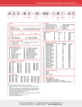
H-Series Circuit Breaker - Flat Rocker Actuator - Ordering Scheme | 5 Series Actuator Poles Circuit Aux/Alarm Actuator Mounting Color & Bezel/Barrier 2 ACTUATOR 1 3 Single Color Vertical 7 Push-to-Reset, Single Color Vertical 4 Single Color Horizontal 8 Push-to-Reset, Single Color Horizontal 8 TERMINAL 1 Push ON 0.250 Tab (Q.C.) 2 Screw 8-32 with upturned lugs Printed Circuitboard Terminals L 90 Facing Left S Straight T Straight, Long 4 CIRCUIT A Switch Only (no coil) C 4 Series Trip (voltage) B Series Trip (current) G 4 Relay Trip (voltage)...
Open the catalog to page 5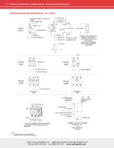
6 | H-Series Circuit Breaker - Handle Actuator - Dimensional Specifications #6-32[M3] THREAD *0.138[3.50] DEEP 2 PLCS PER POLE LOAD TAB (Q.C.) TYPE SCREW TYPE SCREW TYPE TERMINALS IN SERIES TRIP CIRCUIT CONFIGURATION SHOWN. FOR OTHER CONFIGURATIONS,SEE CIRCUIT AND TERMINAL DIAGRAMS. LOAD POLE POLE POLE 1 2 3 MULTI-POLE IDENTIFICATION SCHEME AS VIEWED FROM TERMINAL END OF BREAKER. PANEL CUTOUT DETAIL TOLERANCES ±.005 [±.12] UNLESS OTHERWISE SPECIFIED Notes: 1. ALL DIMENSIONS ARE IN INCHES 1 All dimensions are in inches [millimeters]. [millimeters]. 2 Tolerance ±.020 [.51] unless otherwise specified....
Open the catalog to page 6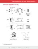
H-Series Circuit Breaker - Curved Rocker Actuator - Dimensional Specifications | 7 #6-32[M3] THREAD *0.138[3.50] DEEP #6-32[M3] THREAD *0.138[3.50] 2 PLCS PER POLE DEEP 2 PLCS PER POLE SCREW TYPE TERMINALS IN SERIES TRIP CIRCUIT CONFIGURATION SHOWN. FOR OTHER CONFIGURATIONS, SEE CIRCUIT AND TERMINAL DIAGRAMS. 1.130 [28.70] 1.130 [28.70] OPTIONAL "ROCKER GUARD" OPTIONAL "ROCKER GUARD" POLE POLE POLE 1 2 3 MULTI-POLE IDENTIFICATION SCHEME AS VIEWED FROM TERMINAL END OF BREAKER. PANEL CUTOUT DETAIL TOLERANCE +.005[+.12] UNLESS OTHERWISE SPECIFIED Notes: 1 All dimensions are in inches [millimeters]....
Open the catalog to page 7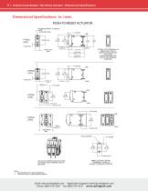
8 | H-Series Circuit Breaker - Flat Rocker Actuator - Dimensional Specifications Dimensional Specifications: in. [mm] PUSH-TO-RESET ACTUATOR #6-32[M3] THREAD *0.138[3.50] DEEP 2 PLCS PER POLE SCREW TYPE TERMINALS IN SERIES TRIP CIRCUIT CONFIGURATION SHOWN. FOR OTHER CONFIGURATIONS, SEE CIRCUIT AND TERMINAL DIAGRAMS. MULTI-POLE IDENTIFICATION SCHEME AS VIEWED FROM TERMINAL END OF BREAKER. PANEL CUTOUT DETAIL TOLERANCE +.005[+.12] UNLESS OTHERWISE SPECIFIED Notes: 1 All dimensions are in inches [millimeters]. 2 Tolerance ±.020 [.51] unless otherwise specified. Email: [email protected] Application...
Open the catalog to page 8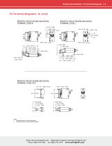
H-Series Circuit Breaker - PC Terminal Diagrams | 9 PC Terminal Diagrams: in. [mm] PRINTED CIRCUIT BOARD MOUNTING TERMINAL CODE R PRINTED CIRCUIT BOARD MOUNTING TERMINAL CODE L PRINTED CIRCUIT BOARD MOUNTING TERMINAL CODE S & T Notes: 1 All dimensions are in inches [millimeters]. 2 Tolerance ±.020 [.51] unless otherwise specified. Email: [email protected] Application Support: [email protected] Phone: (860) 793–9281 Fax: (860) 793–9231 www.carlingtech.c
Open the catalog to page 9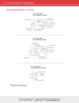
10 | H-Series Circuit Breaker - PC Terminal Diagrams P.C. FOOT PRINT FOR TERMINAL CODE R P.C. FOOT PRINT FOR TERMINAL CODE L P.C. FOOT PRINT FOR TERMINAL CODE S & T Notes: 1 All dimensions are in inches [millimeters]. 2 Tolerance ±.020 [.51] unless otherwise specified. Email: [email protected] Application Support: [email protected] Phone: (860) 793-9281 Fax: (860) 793-9231 www.carlingtech.com
Open the catalog to page 10All Carling Technologies catalogs and technical brochures
 V-Series CONTURA SWITCHES
14 Pages
 641-Series
6 Pages
 Military Catalog
174 Pages
 Marine Catalog
190 Pages
 L-Series Circuit Breaker
8 Pages
 D-Series Circuit Breaker
10 Pages
 CX-Series Circuit Breaker
12 Pages
 Carling CB Catalog
202 Pages
 C-Series Circuit Breaker
26 Pages
 B-Series Circuit Breaker
20 Pages
 A-Series Circuit Breaker
28 Pages
 Carling GFCI
29 Pages
 On-Off Highway Industry
4 Pages
 Military Industry
4 Pages
 V-Series-Contura-X-XI-XII
14 Pages
 V-Series-Contura-XIV
14 Pages
 VP-Series
6 Pages
 W-Series
10 Pages
 700-800-Series
4 Pages
 R135-Series
2 Pages
 V-Series-Rotary
10 Pages
 110-216-Series
4 Pages
 ST-Series
8 Pages
 C-Series
4 Pages
 D-Series
4 Pages
 DK-EK-Series
4 Pages
 F-Series
4 Pages
 G-Series
4 Pages
 H-I-Series
4 Pages
 LT-Series
4 Pages
 MAAOA-215-Series
4 Pages
 BD-Series
10 Pages
 Carling Thermal CB
20 Pages
 TB-Series
6 Pages
 PB-Series
12 Pages
 PC-Series
14 Pages
 V-Charger
6 Pages
 ROCKER SWITCHES
176 Pages
 On-Off Highway Catalog
114 Pages
 Telecom-Datacom Industry
4 Pages
 Renewable Energy
64 Pages
 Renewable Energy Industry
4 Pages
 Medical Equipment Brochure
4 Pages
 On/Off Highway Brochure
4 Pages
 Renewable Energy Brochure
4 Pages
 Marine Brochure
4 Pages
 Telecom/Datacom Brochure
4 Pages
 Military Brochure
4 Pages
 Switches & Controls
172 Pages
 Miniature Switches
84 Pages
 Thermal Circuit Protection
18 Pages
 GFCI/ELCI Circuit Protection
28 Pages


- Single-pole switch
- Push-button switch
- Isolator switch
- Technology switch
- Multipole switch
- Electromechanical switch
- Rotary electric switch
- Rocker switch
- IP67 switch
- Low-voltage main switch
- Touch push-button switch
- Plastic switch
- Action push-button switch
- Form push-button switch
- Metal switch
- Bipolar switch
- Hermetic switch
- Current circuit breaker
- Momentary push-button switch