
- Catalogs
- Carling Technologies
- Carling CB Catalog


Carling CB Catalog

Carling CB Catalog
Carling Technologies specializes in hydraulic-magnetic circuit breakers, offering comprehensive product information and specifications. Their products are known for innovation and reliability, supported by ISO and TS registered manufacturing facilities worldwide.
The catalog includes various circuit protection products such as hydraulic-magnetic, thermal, and ground fault circuit protection. It offers custom design solutions for OEMs and a product selector guide to help choose the right circuit breaker based on several parameters.
Details are provided for different series of circuit breakers, including M-Series, MS-Series, H-Series, and A-Series, highlighting features like number of poles, actuator styles, and current and voltage ratings.
Selection of circuit protection devices requires consideration of load characteristics, voltage rating, phase, poles, national electric codes, interrupting capacity, and mounting requirements. The catalog emphasizes selecting appropriate time delays for startup inrush currents.
Carling Technologies' products comply with standards such as UL, CSA, VDE, and TUV, ensuring safety and reliability.
Carling Technologies offers a robust selection of circuit protection solutions, supported by a global network of technical sales offices and engineers. Customers are encouraged to contact them for further assistance.
Focuses on hydraulic-magnetic circuit protection products, known for precision and reliability, unaffected by ambient temperature changes.
- Thermal Circuit Protectors: Use a bimetallic strip to trip the breaker, sensitive to temperature changes.
- Hydraulic-Magnetic Circuit Protectors/Breakers: Offer precise solutions, stable against temperature changes, with customizable characteristics.
- Equipment Leakage Circuit Breakers: Detect and protect against ground faults using electronic technologies.
These breakers are current sensing devices with a trip-free mechanism, available with various current ratings and configurations, suitable for a wide range of applications.
Common configuration is "Series Trip," with customizable time delay curves for specific applications.
Time delays are achieved by varying fluid viscosity in the delay tube, allowing for different delay curves.
Includes options like Series Trip with Auxiliary Switch, Remote Shutdown, Dual Coil, Relay Trip, and Switch Only.
Outlines specifications for M-Series circuit breakers, including actuator colors, terminal types, and agency approvals.
Instructions for selecting circuit breakers based on current ratings, actuator types, and terminal configurations.
Circuit breakers are UL Recognized, CSA Accepted, and UL Listed, meeting various international standards.
For applications requiring illumination, external resistors must be supplied by the customer.
Provides dimensions and circuit layouts for different breaker configurations.
Tables provide a comprehensive list of current ratings, actuator colors, terminal types, and agency approvals.
Details specifications and features of MS-Series and H-Series circuit breakers, designed for various applications.
Available in 1-3 poles, with current ratings from 0.20 to 30 amps, and voltage ratings of 65VDC, 240VAC, and 120/240VAC.
Available in 1-3 poles, with current ratings from 1 to 35 amps, and voltage ratings of 65VDC, 80VDC, and 250VAC.
Includes detailed ordering schemes for both MS-Series and H-Series circuit breakers.
Carling Technologies' MS-Series and H-Series circuit breakers provide robust solutions for a wide range of applications.
A-Series hydraulic magnetic circuit breakers are known for reliability, compact size, and temperature stability, suitable for OEM markets.
Available in 1-6 poles with ratings from 0.02 to 50 amps, supporting up to 277VAC or 80VDC.
Typical applications include telecom/datacom, marine, military, renewable energy, generators, and welders.
Includes maximum voltage, current ratings, auxiliary switch rating, insulation resistance, and dielectric strength.
Includes endurance, trip-free operation, operating temperature, shock and vibration resistance, and moisture resistance.
Includes options for series, actuator type, number of poles, auxiliary/alarm switch, frequency and delay, current rating, terminal type, actuator color, mounting/barriers, and agency approval.
Certified under various standards including UL 1077, UL 508, UL 1500, CSA, TUV, and VDE.
Provides detailed specifications and ordering information for A-Series Circuit Breakers.
Outlines different series and actuator types, including two-color Visi-Rocker and single-color options.
Options for one, two, or three poles are available.
Various configurations for auxiliary and alarm switches are detailed.
Describes circuit types such as relay trip, series trip, and shunt trip.
Frequency and delay options include DC and 50/60Hz settings.
Comprehensive list of current ratings is provided.
Various terminal configurations are available.
Actuator colors and legends are specified.
Details on mounting options include standard rocker bezels, recessed actuators, and push-to-reset bezels.
Lists certifications such as UL Recognized, CSA Accepted, TUV Certified, and UL489A Listed.
Additional notes provide guidance on specific configurations.
Outlines the ordering scheme for paddle actuators, detailing various specifications.
- Series: Identified by a letter code.
- Actuator: Options include single color recessed paddle actuators with vertical legends.
- Poles: Available in one, two, or three poles.
- Auxiliary Switch: Various configurations including SPDT and SPST with different terminal types.
- Frequency & Delay: Options for DC and 50/60 Hz with various delay settings.
- Current Rating: Ranges from 0.10 to 50.00 amps with specific codes for each rating.
- Terminal: Multiple terminal types including push-on, screw, and printed circuit board terminals.
- Actuator Color: Multiple color options with corresponding legend colors.
- Mounting/Barriers: Different mounting styles with or without barriers.
- Maximum Application Rating: Specific voltage ratings for different configurations.
- Agency Approval: Options include UL recognized, CSA accepted, and others.
Dimensional Specifications
Provides detailed dimensional specifications for various circuit breaker models.
Designed for applications requiring extra insulation and specific construction features.
- Mechanical and Physical: Includes endurance, trip indication, and weight details.
- Environmental: Specifications for shock, vibration, moisture resistance, salt spray, and thermal shock.
- Electrical: Details on maximum voltage, current ratings, auxiliary switch ratings, insulation resistance, and dielectric strength.
Agency Certifications
Lists various agency certifications for the B-Series, including UL, CSA, TUV, and VDE certifications.
Provides detailed specifications and ordering information for B-Series Circuit Breakers.
- Handle Types: Options include single handle per pole, multipole unit handles, and mid-trip handles with or without alarm switches.
- Pole Configurations: Available in configurations from 1 to 4 poles.
- Circuit Codes: Include Series Trip (Current/Voltage), Shunt Trip, Relay Trip, and Dual Coil configurations.
- Current Ratings: Range from 0.020 to 50 amps.
- Terminal Options: Various screw and push-on terminals are available.
- Agency Approvals: UL, VDE, TUV certifications are available depending on the configuration and terminal type.
- Ordering Scheme: Outlines a detailed ordering scheme.
- Use screw terminals for ratings greater than 20 amps.
- Consult the factory for dual coil options.
- Ensure proper use of lock washers for VDE or TUV certifications.
- Some configurations are limited to specific certifications.
- Voltage coils are not rated for continuous duty.
- Tables provide detailed information on current ratings, terminal types, and actuator colors.
- Diagrams illustrate circuit configurations, handle positions, and auxiliary switch modes.
Outlines specifications for TUV and CUL certified circuit breakers, compliant with IEC/EN 60947-2 and CAN/CSA 22.2 No. 5 standards.
Table A provides voltage and current ratings for the TB Series circuit breakers.
Includes a detailed ordering scheme for TB-Series circuit breakers.
Designed for higher amperage and voltage applications, available in 1-6 poles and up to 100 amps.
Comply with MIL-PRF-55629 and MIL-STD-202 standards.
Tables B and C list UL Recognized and CSA Accepted configurations.
Outlines specifications for various circuit breakers, including UL Recognized and CSA Certified ratings.
Details on the construction of shunt and relay trip voltage coils.
Lists various standards and certifications.
Includes consulting the factory for special catalog numbers and dual coil options.
Contains several tables listing configurations, voltage, current ratings, interrupting capacities, and application codes.
Outlines specifications for VAC applications, focusing on multi-pole breakers.
Specifies mounting styles and barriers required for different configurations.
Lists various agency approvals.
Includes consulting the factory for special catalog numbers.
Includes current ratings, actuator colors, and frequency and delay options.
Emphasizes the importance of using barriers on multi-pole units.
Provides detailed specifications and configurations for C-Series and D-Series circuit breakers.
Available with various mounting options.
Lists different terminal types.
Available in multiple colors with specific marking options.
Different maximum application ratings for AC and DC.
Various frequency and delay options are available.
Lists agency approvals such as UL, CSA, and VDE certifications.
Comprehensive table of current ratings is provided.
Detailed dimensional specifications are provided.
Designed for DIN rail mounting and features touch-proof terminals.
Designed to meet MIL-PRF-55629 and MIL-STD-202 specifications.
Provides an ordering scheme for D-Series circuit breakers.
Provides detailed technical specifications and features of the D-Series and G-Series circuit breakers.
All dimensions are provided in inches and millimeters.
Emphasizes features such as wiping contacts and common trip linkage.
Includes optional auxiliary switches and DIN rail locks.
Provides detailed tables listing electrical capabilities.
Designed for endurance with 10,000 ON-OFF operations.
Highlighted for its high performance and compact design.
Supports a maximum voltage of 415Y/240VAC.
Outlines specifications for L-Series and N-Series circuit breakers.
- Dielectric Strength: UL, CSA-1960V 50/60 Hz for one minute.
- Insulation Resistance: Minimum of 100 Megohms @ 500VDC.
- Overload: 50 operations at 600% of rated current.
- Interrupt Capacity: Detailed in Table A.
Environmental Specifications
- Operating Temperature: -40ºC to +85ºC.
- Vibration and Shock: Withstands specified excursions and Gs.
- Thermal Shock and Moisture Resistance: Compliant with standards.
- Salt Spray: Method 101, Condition A.
Mechanical Specifications
- Endurance: 10,000 “On-Off” operations.
- Trip Free and Trip Indication: Breakers trip on overload.
Physical Specifications
- Number of Poles: 1-3 poles for L-Series, 1-2 poles for N-Series.
- Termination: Screw terminals with various thread sizes.
- Materials: Housing made of glass-filled polyester.
Agency Approvals
- UL489, cUL, TUV (EN60934) for L-Series.
- UL489, EN60947-2 for N-Series.
Ordering Scheme
Provides detailed ordering schemes for both L-Series and N-Series circuit breakers.
Outlines dimensional specifications for UL489B circuit breakers.
E-Series hydraulic-magnetic circuit breaker is designed for high current and voltage applications.
Comply with MIL PRF-55629 & MIL-STD-202G standards.
Tables A and B provide detailed configurations and performance capabilities.
UL Recognized, UL Listed, CSA Accepted, and VDE Certified.
Provides a detailed ordering scheme for the E-Series circuit breakers.
Provides detailed specifications and guidelines for selecting power accessories.
- Part Numbers: Examples include 8C1-X0-08-639 for removal tools.
- Accessory Codes: Code '8' is used for accessories.
- Series: Includes C & D-Series and E-Series.
- Sections & Poles: Various configurations.
- Styles and Colors: Options include Carling Logo style.
Accessory Types
- Power Lockout Kit: Designed to allow one section to be live at a time.
- Circuit Breaker Removal Tool: Specific tools for different insert types.
Time Delay Values
Outlines time delay values for various series of circuit breakers.
Provides definitions for key terms such as Alternating Current, Ambient Temperature, Ampacity, Circuit Breaker, and Conductor.
Explains the difference between pulsating DC and AC, and defines current limitation and current rating.
Used by AC ammeters to measure current flow in a wire.
Covers various electrical concepts such as delay, derating, dielectric strength, and grounding.
Defines electromotive force and electromagnetic interference.
Defines faults and describes the role of fuses and circuit breakers.
Frequency is the number of complete cycles per second in an AC current.
Devices designed to protect personnel and equipment by interrupting electric current.
Inductance refers to the temporary storage of energy in magnetic fields.
References the National Electrical Code and the National Electrical Manufacturers Association.
Relates voltage, current, and resistance in a circuit.
Panelboards are central points for power distribution and monitoring.
- Polarity: Ensures correct connection in AC plugs.
- Pole: Refers to conductive paths in switches or relays.
- Potential: Voltage across a circuit element.
- Power: Rate of energy conversion.
- Power Factor: Phase angle shift in AC circuits.
- UL Recognition: Differentiates between UL Recognized and UL Listed devices.
- Rectifier: Converts AC to DC.
- Regulator: Controls output voltage.
- Resistance: Opposition to current flow.
- Reverse Polarity: Dangerous condition where AC system wires are reversed.
- RMS: Method to define effective voltage or current of an AC wave.
- Safety Green Wire: Non-current carrying conductor providing a safe path for fault current.
- Self-Limiting: Device design limits output power.
- Short Circuit: Zero resistance path.
- Short-Circuit Current Rating: Rating in kA with test conditions.
- Sine Wave: Graph of y = sin x.
- Single Phase: 120/240V AC system.
- Stray Current: Unwanted current flows.
- Surge Capacity: Ability to withstand surge currents.
- Switch: Device to open or close an electrical circuit.
- Terminal: Connection point for electrical circuits.
- Thermal: Refers to thermal circuit breakers.
- Time Delay: Intentional delay in protective device operation.
- Total Clearing Time: Time from overload initiation to current interruption.
- Transfer Switch: Selects AC source alternatives.
- Trip Free: Circuit breaker trips under fault current.
- Tripping Current: Coded as a percentage of amp rating.
- Ultimate Trip Current: Minimum current causing protective device tripping.
- Ungrounded Conductor: Not connected to Earth ground system.
- Volt: Unit of electric potential.
- Voltage Drop: Reduction due to conductor resistance.
- Voltage Rating: Maximum operating voltage for a device.
- Voltage Trip: Device calibrated to trip at a specific voltage.
- Watt: Measurement of electrical power.
- Wire Sizing: Selecting conductor size based on current and circuit length.
- Withstand Voltage: Maximum voltage without causing breakdown.
- Details on hydraulic-magnetic circuit breakers, GFCIs/ELCIs, switches, and thermal circuit breakers.
- Specific applications for marine, telecom/datacom, renewable energy, on-off highway, military, and industrial automation.
- Founded in 1920, Carling Technologies manufactures electrical and electronic components.
- Four ISO registered facilities with global sales and engineering teams.
- Environmental, quality, health & safety certifications available online.
Catalog excerpts

Carling Technologies* Innovative Designs. Powerful Solutions. HYDRAULIC-MAGNETIC Circuit Protection
Open the catalog to page 1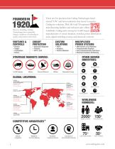
Since its founding, Carling Technologies has continually forged a tradition of leadership in quality and product innovation. There are few products that Carling Technologies hasn’t turned “ON” and fewer industries that haven’t turned to Carling for solutions. With ISO and TS registered manufacturing facilities and technical sales offices worldwide, Carling ranks among the world’s largest manufacturers of circuit breakers, switches, power distribution units, digital switching systems and electronic controls. SWITCHES & CONTROLS • Rocker • Toggle • Pushbutton • Rotary CIRCUIT PROTECTION • Hydraulic-Magnetic •...
Open the catalog to page 2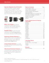
Hydraulic-Magnetic Circuit Protection Carling Technologies’ hydraulic-magnetic circuit breakers are designed to provide maximum circuit protection to a wide variety of applications. Featuring cutting edge designs and advance features, our products are well known for their performance and reliability. Within This Catalog, you will find comprehensive product information for each product series including applications, specifications and ordering schemes. Available Online are tools such as part configurator, product selectors and stock checks. Please visit www.carlingtech.com for the latest information...
Open the catalog to page 3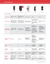
Actuator Style rocker, with or without guard flush rocker, with or without push to reset guard Available Delays AC: ultrashort, short, medium, long, short-high inrush, medium-high inrush, long-high inrush AC: ultrashort, short, medium, long, short-high inrush, medium-high inrush, long-high inrush DC: instant, ultrashort, short, medium & long AC, DC, AC/DC: instant, short, medium & long AC, DC, AC/DC: high inrush-short, medium & long AC, DC: short, medium & long Max Current & Voltage Ratings UL Listed and UL Recognized up to 10,000 amps UL Listed 50000A@80VDC 10000A@125VDC & 240VAC-5KA UL Recognized 5000A@125VDC 5000A@600VAC,...
Open the catalog to page 6
Circuit Protection Introduction Circuit Protection Introduction Any electrical or electronic equipment that is designed without including circuit protection is an accident waiting to happen. Under normal operating conditions, this may not appear to be a problem. However, normal operating conditions are not always guaranteed. Under strained or heavy use, a motor and/or another loadgenerating component within the equipment will draw additional current from the power source; when this happens, the equipment’s wires and/or components will overheat and may ultimately burn up. Also, power surges and...
Open the catalog to page 7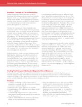
Choices of Circuit Protection / Hydraulic/Magnetic Circuit Breakers Available Choices of Circuit Protection Carling Technologies offers three types of circuit protection devices: thermal circuit protectors, hydraulic-magnetic circuit protectors/breakers and equipment leakage circuit breakers. This catalog features hydraulic-magnetic circuit protection products. For details related to our thermal and ground fault circuit protection product lines, please visit our website. Thermal circuit protectors utilize a bimetallic strip electrically in series with the circuit. The heat generated by the current...
Open the catalog to page 8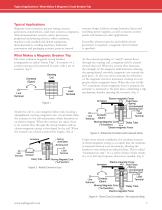
Typical Applications / What Makes A Magnetic Circuit Breaker Trip Typical Applications Magnetic circuit breakers protect wiring, motors, generators, transformers, solid state systems, computers, telecommunications systems, micro-processors, peripheral and printing devices, office machines, machine tools, medical and dental equipment, instrumentation, vending machines, industrial automation and packaging systems, process control systems, lamps, ballasts, storage batteries, linear and switching power supplies, as well as marine control panels and numerous other applications. Generally, wherever...
Open the catalog to page 9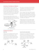
How Time Delays are Obtained / Available Circuit Options How Various Time Delays are Obtained Generally speaking, the trip time of a time delay magnetic circuit breaker is directly related to the length of time it takes for the moving metal core to move to the fully “in” position. If the delay tube is filled with air, the core will move rather quickly, and the breaker will trip quickly. This is characteristic of the Ultrashort Delay Curves #11 and #21. Solid state devices, which cannot tolerate even short periods of current overload, should use Instantaneous Curves #10, #20 and #30. These curves...
Open the catalog to page 10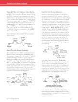
Available Circuit Options Continued Series Mid-Trip with Auxiliary / Alarm Switch Similar to “Series Trip with Auxiliary Switch” except the S.P.D.T. auxiliary switch is actuated only upon electrical trip of the breaker. Upon electrical trip, the “N.O” contact closes and the “N.C” contact opens. This can be used to remotely signal the “TRIPPED” status of the breaker. Also, upon electrical trip, the handle moves to the “MID” position as opposed to the “full OFF” position typical of other breakers. This gives a specific visual panel indication of a “TRIPPED” breaker as compared to one which is merely...
Open the catalog to page 11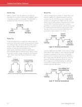
Shunt Trip Switch Only O— Line Terminal Same as a Series Trip, but without a sensing coil. Provides low cost, heavy-duty switch capability when overload protection is not needed. “Switch Only” is available with and without an auxiliary switch. Relay Trip A four terminal device in which the contact and coil circuits are electrically isolated but mechanically linked. An overload in the coil circuit will cause the contact circuit to open. These circuits may be of opposite polarity. Commonly used in dump circuit, panic circuit, and remote shutdown applications. (Note: World Approval Agencies may...
Open the catalog to page 12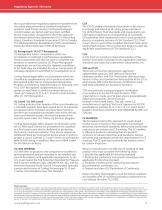
Regulatory Agencies / Warranty Most countries have regulatory agencies that determine the safety and performance standards required for products used in that country. Carling Technologies’ circuit breakers are tested and have been certified by the most widely recognized of the these agencies including Underwriters Laboratories (UL) in the United States; Canadian Standards Association (CSA) in Canada; TUV Rheinland/Berlin-Brandenburg (TUV) and Verband Deutscher Elektrotechniker (VDE) in Germany. UL Recognized / UL1077 Recognized UL Recognition covers components, which are incomplete or restricted...
Open the catalog to page 13All Carling Technologies catalogs and technical brochures
 V-Series CONTURA SWITCHES
14 Pages
 641-Series
6 Pages
 Military Catalog
174 Pages
 Marine Catalog
190 Pages
 L-Series Circuit Breaker
8 Pages
 H-Series
14 Pages
 D-Series Circuit Breaker
10 Pages
 CX-Series Circuit Breaker
12 Pages
 C-Series Circuit Breaker
26 Pages
 B-Series Circuit Breaker
20 Pages
 A-Series Circuit Breaker
28 Pages
 Carling GFCI
29 Pages
 On-Off Highway Industry
4 Pages
 Military Industry
4 Pages
 V-Series-Contura-X-XI-XII
14 Pages
 V-Series-Contura-XIV
14 Pages
 VP-Series
6 Pages
 W-Series
10 Pages
 700-800-Series
4 Pages
 R135-Series
2 Pages
 V-Series-Rotary
10 Pages
 110-216-Series
4 Pages
 ST-Series
8 Pages
 C-Series
4 Pages
 D-Series
4 Pages
 DK-EK-Series
4 Pages
 F-Series
4 Pages
 G-Series
4 Pages
 H-I-Series
4 Pages
 LT-Series
4 Pages
 MAAOA-215-Series
4 Pages
 BD-Series
10 Pages
 Carling Thermal CB
20 Pages
 TB-Series
6 Pages
 PB-Series
12 Pages
 PC-Series
14 Pages
 V-Charger
6 Pages
 ROCKER SWITCHES
176 Pages
 On-Off Highway Catalog
114 Pages
 Telecom-Datacom Industry
4 Pages
 Renewable Energy
64 Pages
 Renewable Energy Industry
4 Pages
 Medical Equipment Brochure
4 Pages
 On/Off Highway Brochure
4 Pages
 Renewable Energy Brochure
4 Pages
 Marine Brochure
4 Pages
 Telecom/Datacom Brochure
4 Pages
 Military Brochure
4 Pages
 Switches & Controls
172 Pages
 Miniature Switches
84 Pages
 Thermal Circuit Protection
18 Pages
 GFCI/ELCI Circuit Protection
28 Pages


- Single-pole switch
- Push-button switch
- Technology switch
- Isolator switch
- Multipole switch
- Electromechanical switch
- Rotary electric switch
- Rocker switch
- IP67 switch
- Touch push-button switch
- Action push-button switch
- Form push-button switch
- Metal switch
- Plastic switch
- Hermetic switch
- Bipolar switch
- Current circuit breaker
- Momentary push-button switch
- Technology push-button switch
- VirtualExpo Group
- Our Partners
- Recruitment
- Testimonials