- Catalogs
- Carling Technologies
- B-Series Circuit Breaker
B-Series Circuit Breaker
1 /20Pages

B-Series Circuit Breaker
1 /20Pages
Catalog excerpts

B-SeriesCIRCUIT BREAKER Carling Technologies’ B-Series hydraulic magnetic circuit breakers are specifically designed for applications requiring extra insulation and tongue and groove half-shell constructions. The B-Series carries global regulatory safety approvals for spacing requirements and are ideal for use as general purpose as well as full load amp applications. Available with various choices of time delays, terminals, actuator styles, with a wide range of standard colors and imprinting. Product Highlights: ♦ Meet CSA Standard 22.2 No. 100 for the Generator & Welder markets ♦ Extra insulation and tongue & groove half-shell constructions ♦ UL Recognized - UL Standard 508, 1077, 1500 ♦ UL Listed - UL Standard 489, 489A ♦ CSA Accepted ♦ TUV Certified ♦ VDE Certified Typical Applications: Power Supplies Medical Equipment Generators & Welders Office Equipment Control Panels Marine Military Carling Technologies8 Innovative Designs. Powerful Solutions. Carling Technologies, Inc. 60 Johnson Avenue, Plainville, CT 06062 Email: [email protected] Application Support: [email protected] Phone: 860.793.9281 Fax: 860.793.9231
Open the catalog to page 1
2 | B-Series Circuit Breaker - General Specifications Electrical Mechanical Maximum Voltage Current Ratings Standard Voltage Coils Auxiliary Switch Rating Insulation Resistance Dielectric Strength Resistance, Impedance 277VAC 50/60 Hz, 80VDC Standard current coils: 0.100, 0.250, 0.500, 0.750, 1.00, 2.50, 5.00, 7.50, 10.0, 15.0, 20.0, 25.0, 30.0, 35.0, 40.0 and 50.0 amps. Other ratings available, see ordering scheme. DC - 6V, 12V; AC - 120V, other ratings available, see ordering scheme. SPDT; 10.1 AMPS - 250VAC,1.0A 65 VDC or 0.5A 80 VDC, 0.1 Amps - 125VAC (with gold contacts). VDE-1.0 Amp - 125VAC. Minimum...
Open the catalog to page 2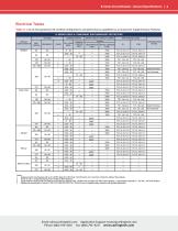
B-Series Circuit Breaker - General Specifications | 3 B -SERIES TABLE A: COMPONENT SUPPLEMENTARY PROTECTORS CIRCUIT CONFIGURATION Notes: 1 Requires branch circuit backup with a UL LISTED Type K5 or RK5 fuse (15A minimum) at no more than 4 times the rating of the protector. 2 Same as note 1, except that backup fuse is limited to 80A maximum. 3 2 pole protector required (with one pole per power line) for: 250/125 VAC, 125/250 VAC and 208Y/120 VAC Power Systems. 1 pole protector required for : 125 VAC, 10 Power System. 4 Satisfies the requirements of clause 11.2.8.2.5 of CSA STD C22.2 No 100...
Open the catalog to page 3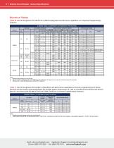
4 | B-Series Circuit Breaker - General Specifications Electrical Tables Table B: Lists UL Recognized, CSA, VDE & TUV Certified configurations & performance capabilities as a Component Supplementary Protector. B-SERIES TABLE B: COMPONENT SUPPLEMENTARY PROTECTORS Notes: 1 Available with special catalog number only (consult factory). 2 2 pole protector required (with one pole per power line) for: 250/125 VAC, 125/250 VAC and 208Y/120 VAC Power Systems. 1 pole protector required for : 125 VAC, 10 Power System. Email: [email protected] Application Support: [email protected] Phone: (860)...
Open the catalog to page 4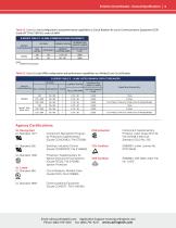
Table D: Lists UL Listed configurations and performance capabilities as Circuit Breakers for use in Communications Equipment (CCN/ Guide DITT, File E189195), under UL489A B-SERIES TABLE D: UL489A (COMMUNICATIONS EQUIPMENT) Component Recognition Program as Protectors Supplementary (Guide CCN/QVNU2, File E75596) Switches, Industrial Control (Guide CCN/NRNT2, File E148683) Protectors, Supplementary for Marine Electrical & Fuel Systems (Guide PEQZ2, File E75596) Ignition Protection Circuit Breakers, Molded Case, (Guide DIVQ, File E129899) TUV Certified A VDE Certified Component Supplementary Protector...
Open the catalog to page 5
6 | B-Series Circuit Breaker - Handle UL Recognized - Ordering Scheme Series Actuator Poles Circuit Aux/Alarm Frequency Terminal Actuator Mounting/ Agency Color Barriers Approval 2 ACTUATOR A Handle, one per pole B Handle, one per multipole unit S Mid-Trip Handle, one per pole T Mid-Trip Handle, one per pole & Alarm Switch 4 CIRCUIT A 2 Switch Only (No Coil) B Series Trip (Current) C Series Trip (Voltage) D 3 Shunt Trip (Current) E 3 Shunt Trip (Voltage) F 3 Relay Trip (Current) G 3 Relay Trip (Voltage) H 3,4 Dual Coil with Shunt Trip Voltage Coil K 3,4 Dual Coil...
Open the catalog to page 6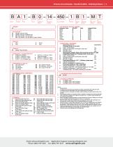
B-Series Circuit Breaker - Handle UL489A - Ordering Scheme | 7 Series Actuator Poles Circuit Aux/Alarm Terminal Actuator Mounting/ Color Barriers Max. Appl. Agency Rating Approval 9 ACTUATOR COLOR & LEGEND 2 ACTUATOR 1 A Handle, one per pole B Handle, one per multipole unit S Mid-Trip Handle, one per pole T Mid-Trip Handle, one per pole & Alarm Switch Actuator Color White Black Red Green Blue Yellow Gray Orange ON-OFF B D G J Legend Color Black White White White White Black Black Black (Gold Contacts) 8 S.P.S.T., 0.187 Q.C. Term. 4 CIRCUIT B Series Trip (Current)...
Open the catalog to page 7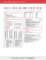
8 | B-Series Circuit Breaker - Handle UL489 Listed - Ordering Scheme Series Actuator Poles Circuit Aux/Alarm Terminal Actuator Mounting/ Color Barriers Max. Appl. Agency Rating Approval 1 SERIES B 9 ACTUATOR COLOR & LEGEND 6 ON-OFF B 2 ACTUATOR 1 A Handle, one per pole B Handle, one per multipole unit S Mid-Trip Handle, one per pole T Mid-Trip Handle, one per pole & Alarm Switch Actuator Color White Black Red Green Blue Yellow Gray Orange Legend Color Black White White White White Black Black Black 4 CIRCUIT B Series Trip (Current) 5 AUXILIARY / ALARM SWITCH 4 0 without...
Open the catalog to page 8
B-Series Circuit Breaker - Handle - Circuit & Terminal Diagrams | 9 Circuit & Terminal Diagrams: in. [mm] HANDLE POSITION VS. AUX/ALARM SWITCH MODE Notes: 1 All dimensions are in inches [millimeters]. 2 Tolerance ±.020 [.51] unless otherwise specified. 3 Alarm Switch available with .110 x .020 Q.C. & Solder Lug Terminals Only.
Open the catalog to page 9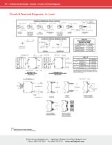
10 | B-Series Circuit Breaker - Handle - Circuit & Terminal Diagrams TABLE A TIGHTENING TORQUE SPECIFICATIONS UL-489 MULTI-POLE UL-RECOGNIZED MULTI-POLEBREAKERS BREAKERS M6STUD AVAILABLE ON SERIES TRIP AND SWITCH ONLY CIRCUITS. WHEN CALLED FOR ON MULTI-POLE UNITS, ONLY ONE AUX. SWITCH IS NORMALLY SUPPLIED, AS SHOWN IN MULTI-POLE IDENTIFICATION SCHEME. PUSH-IN STUD SCREWTERMINAL WITH 30° BEND BACKCONNECT SCREWTERMINAL BACKCONNECT SCREW TERMINAL WITH RETAINER Notes: 1 All dimensions are in inches [millimeters]. 2 Tolerance ±.020 [.51] unless otherwise specified.
Open the catalog to page 10All Carling Technologies catalogs and technical brochures
 V-Series CONTURA SWITCHES
14 Pages
 641-Series
6 Pages
 Military Catalog
174 Pages
 Marine Catalog
190 Pages
 L-Series Circuit Breaker
8 Pages
 H-Series
14 Pages
 D-Series Circuit Breaker
10 Pages
 CX-Series Circuit Breaker
12 Pages
 Carling CB Catalog
202 Pages
 C-Series Circuit Breaker
26 Pages
 A-Series Circuit Breaker
28 Pages
 Carling GFCI
29 Pages
 On-Off Highway Industry
4 Pages
 Military Industry
4 Pages
 V-Series-Contura-X-XI-XII
14 Pages
 V-Series-Contura-XIV
14 Pages
 VP-Series
6 Pages
 W-Series
10 Pages
 700-800-Series
4 Pages
 R135-Series
2 Pages
 V-Series-Rotary
10 Pages
 110-216-Series
4 Pages
 ST-Series
8 Pages
 C-Series
4 Pages
 D-Series
4 Pages
 DK-EK-Series
4 Pages
 F-Series
4 Pages
 G-Series
4 Pages
 H-I-Series
4 Pages
 LT-Series
4 Pages
 MAAOA-215-Series
4 Pages
 BD-Series
10 Pages
 Carling Thermal CB
20 Pages
 TB-Series
6 Pages
 PB-Series
12 Pages
 PC-Series
14 Pages
 V-Charger
6 Pages
 ROCKER SWITCHES
176 Pages
 On-Off Highway Catalog
114 Pages
 Telecom-Datacom Industry
4 Pages
 Renewable Energy
64 Pages
 Renewable Energy Industry
4 Pages
 Medical Equipment Brochure
4 Pages
 On/Off Highway Brochure
4 Pages
 Renewable Energy Brochure
4 Pages
 Marine Brochure
4 Pages
 Telecom/Datacom Brochure
4 Pages
 Military Brochure
4 Pages
 Switches & Controls
172 Pages
 Miniature Switches
84 Pages
 Thermal Circuit Protection
18 Pages
 GFCI/ELCI Circuit Protection
28 Pages


- Single-pole switch
- Push-button switch
- Isolator switch
- Technology switch
- Multipole switch
- Electromechanical switch
- Rotary electric switch
- Rocker switch
- IP67 switch
- Low-voltage main switch
- Touch push-button switch
- Plastic switch
- Action push-button switch
- Form push-button switch
- Metal switch
- Bipolar switch
- Hermetic switch
- Current circuit breaker
- Momentary push-button switch