
Catalog excerpts

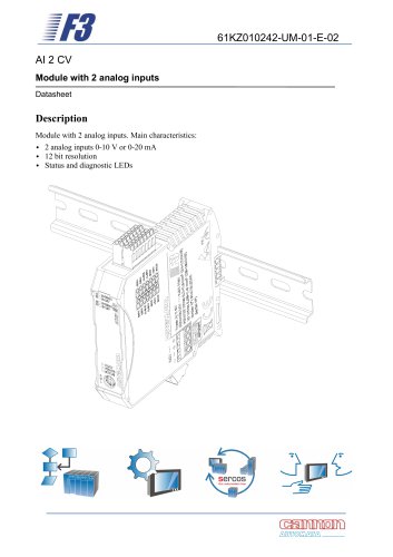
61KZ010247-UM-01-E-01 DO 4 P Module with 4 digital outputs Datasheet Description Module with 4 digital outputs. Main characteristics: • 4 digital outputs • Maximum output current: 2 A for each output, 7 A total • Overcurrent and overtemperature protection • Status and diagnostic LEDs TBus Connector Front Panel Power Supply Conn
Open the catalog to page 1
General data Power supply
Open the catalog to page 3
The module has two connectors: a power connector and an I/O connector. They allow easy “plug and play” of the module, and also a fast replacement of a faulty unit. Power connector The power connector is located on the bottom wall of the module. For the pinout, refer to the illustration. Its function is to provide the supply for the I/O circuitry, whilst the CPU of the module is fed by the TBUS connector on the back of the unit.
Open the catalog to page 5
I/O connector Located on the upper side of the module, this connector (see illustration) permits the wiring of the actuators. As you can see from the illustration, each row of the connector has the same pinout, to ease the wiring and prevent mistakes. Connection notes The connection scheme differs slightly depending on the actuator itself. In more detail, the wiring is different using 1-wire, 2-wire, 3-wire and 4-wire devices (see illustrations in the following pages). The sum of the current provided by the outputs and the supply current for the loads (if provided by the I/O connector) must...
Open the catalog to page 6
SHLD to external ground optional ACTUATOR Recommended wiring for 1-wire (above, on the left), 2-wire (above, on the right), 3-wire (below, on the left) and 4-wire (below, on the right) actuators.
Open the catalog to page 7
Each module is provided with a series of LED lamps on the front panel (see illustration), that indicates the status of the unit, the logic state of every output and a possible diagnostic warning. For the sake of clarity, different lamp colours are employed. The green power (POWER) LED is lighted if the 24 V supply (VM) is present and the internal fuse is not blown. The DO-01 to DO-04 orange LEDs indicate, if lighted, that the corresponding output logical level is “1”. The status of the unit is indicated by both status (STATUS) and fault (FAULT) LEDs.
Open the catalog to page 8
Module addressing and protocol data Address setting Any bus channel can bear a maximum of 15 different modules. The system (namely the bus coupler) distinguishes each of them by a numerical address. So, when a new unit is installed, it’s necessary to set the address of it by a rotary switch fitted on the front panel. The operation is easily done opening the transparent plastic cover and turning the rotor with a small bladed screwdriver. Warning: The useable addresses are those from 1 to 15 (F in hexadecimal notation); address 0 is forbidden. A module with address 0 will not be recognized by...
Open the catalog to page 9All Cannon-Automata catalogs and technical brochures
-
 I/O MODULE 2
10 Pages
-
 F3 Net
2 Pages
-
 F3
F32 Pages
-
 AO2CV
AO2CV10 Pages
-
 I/O MODULE 2 analog inputs
10 Pages
-
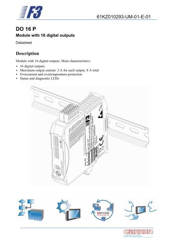 I/O MODULE 16 digital outputs
11 Pages
-
 L1/C1-Flyer
6 Pages