- Catalogs
- Canalta Controls Ltd.
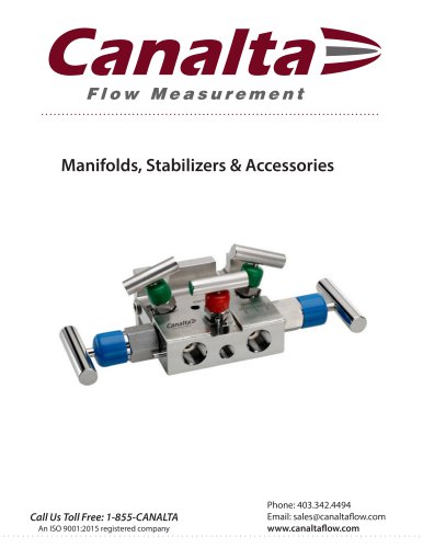
- The Canalta Single Chamber Orifice Fitting
The Canalta Single Chamber Orifice Fitting
1 /15Pages
The Canalta Single Chamber Orifice Fitting
1 /15Pages
Catalog excerpts
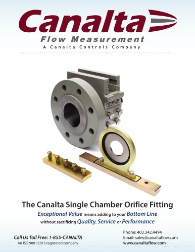
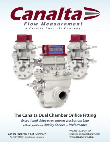
Flow Measurement A Canalta Controls Company The Canalta Single Chamber Orifice FittingExceptional Value means adding to your Bottom Line without sacrificing Quality, Service or Performance Call Us Toll Free: 1-855-CANALTA Phone: 403.342.4494 Email: [email protected]
Open the catalog to page 1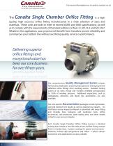
For more information or to order, contact us at Canalta Flow Measurement quality, high accuracy orifice fitting manufactured in a wide selection of sizes and materials. These units are built to meet or exceed ASME and ANSI specifications, as well as to comply with the requirements of the latest editions of AGA-3 / API-14.3 and ISO-5167. Whatever the application, your process will benefit from Canalta's proven reliability and can improve your bottom line without sacrificing quality, service or performance. Delivering superior orifice fittings and exceptional value has been our core business for...
Open the catalog to page 2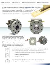
Email: [email protected] | Web: www.canaltaflow.com All Single Chamber Orifice Fittings come standard with HNBR O-ring seals on the seal bar. This feature provides you with superior sealing capability while eliminating nuisance gasket maintenance and clamping bar screw breakage. The O-rings incorporated are standard shelf sizes and can be supplied in a wide variety of compositions. Gaskets are also available and can be used when preferred or required. Single Chamber Orifice Fitting models 8” and larger incorporate a rack and pinion gear system to manage the sizeable weight of large orifice...
Open the catalog to page 3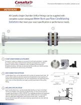
For more information or to order, contact us at An ISO 9001:2015 Registered Company METER RUNS All Canalta Single Chamber Orifice Fittings can be supplied with complete custom-designed Meter Runs and Flow Conditioning Solutions that meet your exact specification or performance needs. 1 2 FLOW CONDITIONING ACCESSORIES The goal of meter run design is to account for swirl and turbulence. Suitable for a wide range of flow measurement methods and equipment, Canalta’s Contour™ lineup of Flow Conditioners, Flow Conditioner Housings and Straightening Vanes will help you develop the flow profile you need...
Open the catalog to page 4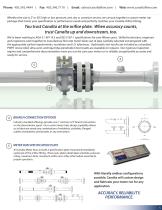
Email: [email protected] | Web: www.canaltaflow.com Whether the size is 2” or 30”, high or low pressure, wet, dry or corrosive service, we can put together a custom meter run package that meets your specification or performance needs and perfectly matches your Canalta Orifice Fitting. You trust Canalta at the orifice plate. When accuracy counts, trust Canalta up and downstream, too. We’ve been working to AGA-3 / API 14.3 and ISO 5167-1 specifications for over fifteen years. Skilled technicians, engineers and inspectors work together to manufacture first-rate meter tubes out of pipe carefully...
Open the catalog to page 5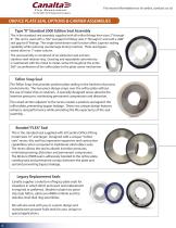
For more information or to order, contact us at An ISO 9001:2015 Registered Company ORIFICE PLATE SEAL OPTIONS & CARRIER ASSEMBLIES Type “K” Standard 2000 Edition Seal Assembly This is the standard seal assembly supplied with all orifice fittings from sizes 2” through 8”. This unit is used with a .562” seal gap for fittings sizes 2” through 6”, and with a .688” seal gap for 8” fittings. The single downstream seal function offers superior sealing capability while reducing seal damage during insertion. Plate seal bypass tested down to 1” water column. The seal assembly is comprised of an elastomer...
Open the catalog to page 6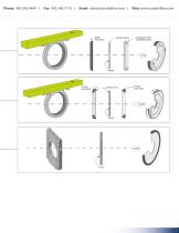
Email: [email protected] | Web: www.canaltaflow.com HNBR SEAL RING ORIFICE PLATE STAINLESS STEEL RETAINING RING TEFLON SNAP RING ORIFICE PLATE TEFLON SNAP RING
Open the catalog to page 7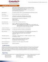
For more information or to order, contact us at An ISO 9001:2015 Registered Company TECHNICAL SPECIFICATIONS Design . . . . . . . . . . . . . . . . . . . . . . . Orifice fittings supplied in Canada are built in accordance with the ABSA Quality Control Program and carry a CRN registration number. Industry Canada Approval Number AF-0014. In compliance with ASME 16.34 and ASME 16.5, ASTM specifications, AGA-3 Latest Edition and ISO-5167. Body Materials . . . . . . . . . . . . . . . A216 WCB, A216 WCC, A352 LCC, A358 CF8M, A995 Gr4A, A995 Gr6A, Custom Internal Parts . . . . . . . . . . . . . . ....
Open the catalog to page 8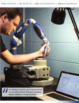
Phone: 403.342.4494 | Fax: 403.346.7110 | Email: [email protected] | Web: www.canaltaflow.com Our Quality Control systems guarantee that your Canalta Orifice Fittings are service ready, reliable and truly accurate. 9
Open the catalog to page 9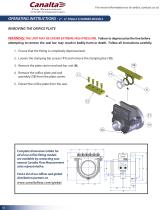
For more information or to order, contact us at An ISO 9001:2015 Registered Company OPERATING INSTRUCTIONS - 2” - 6” SINGLE CHAMBER MODELS REMOVING THE ORIFICE PLATE WARNING: THE UNIT MAY BE UNDER EXTREME HIGH PRESSURE. Failure to depressurize the line before attempting to remove the seal bar may result in bodily harm or death. Follow all instructions carefully. 1. Ensure that the fitting is completely depressurized. 2. Loosen the clamping bar screws (11) and remove the clamping bar (12). 9B 3. Remove the plate carrier and seal bar unit (8). 4. Remove the orifice plate and seal assembly (13)...
Open the catalog to page 10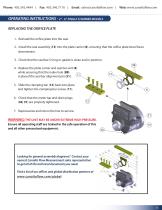
Email: [email protected] | Web: www.canaltaflow.com OPERATING INSTRUCTIONS - 2” - 6” SINGLE CHAMBER MODELS REPLACING THE ORIFICE PLATE 1. Reinstall the orifice plate into the seal. 2. Install the seal assembly (13) into the plate carrier (8), ensuring that the orifice plate bevel faces downstream. 3. Check that the seal bar O-ring or gasket is clean and in position. 9B 4. Replace the plate carrier and seal bar unit (8) while ensuring that the index hole (9B) 11 is placed the seal bar alignment pin (51). 5. Slide the clamping bar (12) back into place and tighten the clamping bar screws (11)....
Open the catalog to page 11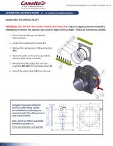
For more information or to order, contact us at Canalta Flow Measurement OPERATING INSTRUCTIONS - 8" - 16" single chmmerrmodels WARNING: THE UNIT MAY BE UNDER EXTREME HIGH PRESSURE. Failure to depressurize the line before attempting to remove the seal bar may result in bodily harm or death. Follow all instructions carefully. 1. Ensure that the fitting is completely depressurized. 2. Loosen the clamping bar screws (11). 3. Remove the clamping bar (12) and seal bar 4. Rotate the plate carrier pinion gear (5) to raise the plate carrier assembly. 5. Remove the orifice plate (13) and seal assembly...
Open the catalog to page 12All Canalta Controls Ltd. catalogs and technical brochures
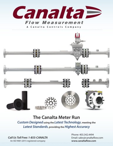 The Canalta Meter Run
4 Pages
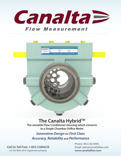 The Canalta HybridTM
4 Pages
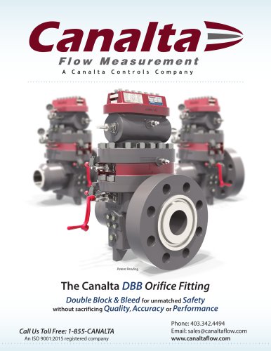 The Canalta DBB Orifice Fitting
24 Pages
- Accanto valve
- Accanto manual valve
- Flowmeter
- Volume flow monitor
- Liquid flow monitor
- Flange valve
- Stainless steel flow monitor
- Carbon steel valve
- Compact flow monitor
- Process valve
- DN50 - 2" flow meter
- Flange flow meter
- Metal valve
- DN100 - 4" flow meter
- Flange valve
- Vertical flow meter
- DN300 - 12" flow meter
- Horizontal flow meter
- Analog counter
- Blowdown valve