

VERTICAL SLOTTINC MACHINES
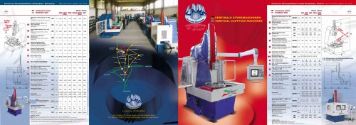
VERTICAL SLOTTINC MACHINES
Technical Specifications Overview
The document presents a series of numerical data and parameters likely related to industrial machinery, specifically cutting machines (stozzatrici) from 8C..A.M.S. srl, an Italian company.
Dimensions and Physical Parameters
- Various measurements are provided, including lengths (L), heights (H), and pressures (P), with typical values such as P=2500 to 3800, L=2300 to 3200, and H=3200 to 4900 (units not specified but likely millimeters or similar).
- Diameter values (Ø) are given, ranging from Ø190 to Ø1000, indicating sizes of components or tooling.
- Additional dimensions include rectangular sizes like 600x700, possibly referring to machine openings or work areas.
Performance and Power Parameters
- Power ratings or operational ranges are indicated, such as inverter ranges from 10 to 50 and brushless motor ranges from 0 to 80.
- Power supply types are noted as 3AC and 4AC, with power values around 5.5 (likely kW).
- Load or capacity values range from 4600 to 10000, possibly indicating weight or force capacities.
Material and Component Specifications
- Repeated numeric sequences suggest specifications for components or materials, including thicknesses, weights, or capacities (e.g., 800, 1100, 1500; 650, 700, 900; 310, 470, 735).
- Some values appear to be related to operational parameters such as speed or torque (e.g., 4.5, 16.5, 6.7, 28).
Manufacturer and Contact Information
The document references 8C..A.M.S. srl, located in Santa Giustina in Colle (Padova), Italy, with contact details including telephone +39 049 5790272, email [email protected], and website www.cams.it.
Summary of Critical Information
- Pressure (P): Ranges from 2500 to 3800 units.
- Dimensions (L x H): Lengths from 2300 to 3200, heights from 3200 to 4900.
- Diameter (Ø): Components sized between 190 mm and 1000 mm.
- Power Supply: 3-phase and 4-phase AC, with power ratings around 5.5 kW.
- Motor Types: Inverter and brushless motors with operational ranges specified.
- Load Capacities: Values up to 15000, indicating machine capacity or force.
Interpretation and Recommendations
The data appears to be a technical specification sheet for industrial cutting machines, detailing mechanical dimensions, power requirements, and operational parameters. For practical application, users should verify units and confirm compatibility with their operational needs. The contact information allows for direct inquiry for detailed technical support or customization.
Catalog excerpts
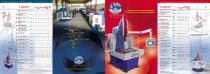
Rack and pinion system ram drive Antrieb des Werkzeugschlittens mitteis Pleuelstange / Handrad Rod and Crank system ram drive TECHNISCHE OATEN SB TECHNICAL DATA Modelle /Models TECHNISCHE OATEN 3G TECHNICAL DATA Modelle /Models Regelbarer Werkzeughub von Null bis Adjustable cool stroke from zero to 4AC = Langsar.nse Y (NC) ♦ Querachse X (NC) + Drehiischschse A (NC) * Achse Z - Stosselhuo (NCi. 4AC wAuiq table toed m working direction (axis Y) • sideways fans X) • electronic rotary table (axis A) * ram axis (axis Z) D«»se Vmottwitttchung und «ts«U1 *H*f torfwngea Ausgaben und modifizierten V«vo«n. Alla angehlhrtnn Wf*rt« *wd RicfifwrrlM und mmuI von unseiov Seta am unvwhmdkch Ww bohaiten uns das Rechi vor. onno vorheitge Anklindigung Anderungen vofzunthmen. Eine Ver vietfabigung. wenn auch nor auswgvvwise. «af ohne Genehmigutig verbolan 7>.* pub'icatioa cancel and replaces any previous edition and rewston. At' kstod data me appronmate ana it s undo*stood that ttnt entails no oON.gaJior on out pan \Ve ftse~te fte tight to impiermni mcxtilcalions without notice. This catalogue cannot be reproduced, even partially, without prior content. S. Giorgio doll* Partlche VERTIKALE STOSSMASCHINEN VERTICAL SLOTTING MACHINES Regelbarer Werkzeughub von Null bis_ Adjustable Tool stroke Irom zero to Abstand zwischen Saule und A Werkzeugtrager Distance between column and tool-holder Abstand Tischoberseite StoOkopf Distance between table surface and head Abstand Tischoberseite -Hallenboden Distance between table surface and earth Abstand Werkzeugmitte -Tischmitte (Bedienerseite) Distance between toolholder basis and table center backwards Via S. Stefano,10 - Santa Giustina in Colle (Padova) Italia Tel. +39 049 5790272 - e-mail: [email protected] - web site: www.cams.it 2AC/3AC Abstand Werkzeugmitte -Tischmitte (Standerseite) Distance between toolholder basis and table center forwards Rectangular table dimensions Hole in table center Rotary table working diameter [axis A] Max. Abstand Werkzeugaufnahme - Schlitten im OTP Max distance between head surface end ram surface (HDP) Max. Abstand Werkzeugaufnahme • Schlitten im UTP Max distance between head surface and ram surface [LHP] Maximale Tisch-Belastbarkeit Langsweg (Y-Achse) Longitudinal table travel (axis V] Querweg (X-Achse) Cross-table travel (axis X) Overall dimensions Anzahl der regelbaren StoBe (mitteis Inverter] von bis Steplessly variable strokes per minute Mam motor power ot ram movement (auto-braking asyncronous] Mam motor power ot ram movement (brushless] Approximate weight LEGENDE/ LEGEND: 3AC * Unoi»rtis» 1 (NCI * Quwauiw X (NC) - OretMisctiachM A INC) 2AC *AjjIo tibh teed m wv*kmg duecPOh (utis Y) * mdowtys (ms X). 3AC * Ajto table feed m working direction (in* r) • sideways (axis X) * electronic rotary table (avs A)
Open the catalog to page 1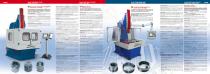
CAMS STOSSMASCHINEN Modelle 400, 500 CAMS SLOTTING MACHINES Models 40C, 500 CAMS STOSSMASCHINEN Modelle 4QCE, 5QOE, 850 CAMS SLOTTING MACHINES Models 4CQE, 500E, 850 4AC Antrieb des Werkzeugschlittens mittels Pleuelstange / Handrad Der auBergewohnliche Anwendungsbereich der StoBmaschinen Mod.400 und 500 ist das Ergebnis langjahriger Erfahrung unserer Techniker in Verbindung mit den Vorschlagen und Anregungen unserer anspruchsvollsten Kunden. MASCHINENRAHMEN Der ganze Rahmen ist aus stabilem, geschweiBtem und spannungsfrei warmebehandeltem Stahl gefertigt worden. KOPF und SCHLITTEN: Aus Gusseisen...
Open the catalog to page 2All CAMS srl catalogs and technical brochures
 Slotting tool round series
2 Pages


Archived catalogs
 CAMS SLOTTING MACHINES
2 Pages