

Scanner 1141

Scanner 1141
The NUFLO Scanner 1141 RTU is a versatile hardware device used for monitoring and data collection in industrial settings, particularly in natural gas production. It supports multiple gas measurement protocols and includes an audit trail for data integrity. The device is certified for use in hazardous areas and integrates with a multi-variable transducer for precise measurement of static and differential pressure, and temperature.
- Data Storage: Stores up to 60 days of flow history with an audit trail, secured by a lithium backup battery.
- Power Supply: Includes a rechargeable battery module with solar charging and options for 12Vdc and 5-VDC supplies.
- Communication: Supports local and remote communication via radio, modem, phone, and satellite.
- Security: Offers five security levels and configurable display options.
- Calibration and Control: Provides methods for device calibration and includes controllers for proportional/integral control.
Installation involves securing the enclosure, unpacking, mounting, and connecting the scanner to piping. It also includes setting up a solar panel and connecting the power supply or charge controller. Proper installation is crucial for optimal performance.
Details the wiring of major components, including switches, jumpers, potentiometers, and field wiring termination. It provides instructions for connecting various inputs and outputs, such as analog and frequency pulse inputs.
The startup procedure includes superbooting the scanner and following setup steps for calibration, with a focus on MVT calibration for accurate measurements.
Includes tools required for troubleshooting, common problems and solutions, and procedures for returning the scanner for service and replacing the battery.
Provides a detailed list of parts and order codes for different models of the Scanner 1141.
Includes general specifications, environmental conditions, enclosure details, computer and display specifications, and communication ports.
The Scanner 1141 maintains an event log as a circular buffer, storing up to 100 events. The user change log halts further changes when full until downloaded, ensuring a continuous audit trail.
Before handling electronic circuit boards, power to the Scanner 1141 must be turned off to prevent damage. Circuit boards should be handled in a static-free environment, and operators must be grounded.
The display can be turned on by pressing the SW8 button. The contrast and brightness of the LCD display are adjustable via potentiometers.
The CN20 jumper manages the lithium backup battery for NVRAM, which should be set to ON during operation to prevent data loss.
Includes various switches and jumpers for configuring pulse inputs, initiating a 'superboot', and programming FLASH memory.
Provides options for 4-20 mA analog output and programming the FPGA boot block.
Includes important safety warnings for RTD installations to prevent explosion hazards.
The Scanner 1141 provides excitation, with debouncing circuitry limiting input frequency to a maximum of 15 Hz.
This mode connects directly to a variable-reluctance pickup coil, used in NuFlo gas and liquid turbine meters.
Resources handle status inputs and outputs, with passive inputs using an internal power source.
An optional 4-20 mA output is available, requiring terminals 39 and 40.
Accessed through a 4-pin connector, typically used with a PC.
Configurable for RS-485, RS-232C, or TTL communications.
Ensure non-hazardous conditions before connecting a PC. Follow specific steps for power connection, firmware verification, and superbooting.
- Display and Contrast Adjustment: Use a slotted screwdriver to adjust the contrast potentiometer on the mainboard.
- Scanner Communication Issues: Ensure the console port cable is connected and the correct COM port is displayed.
- Battery Charging Problems: Check the charging voltage and connections.
- Network Port Functionality: Verify network settings and ensure the network is enabled.
- MVT Cell Signal Issues: Confirm MVT hardware allocation and check zero/full-scale values.
- Various voltage supplies are detailed, including Vcc (5V), VPP (0V), VPR (5V), VMSP (3.3V), and others.
- Ensure the NVRAM lithium battery voltage is above 2.0 VDC.
- Detailed parts list for Scanner 1141 models.
Outlines specifications for communication ports, power supplies, and input/output configurations.
Designed for use with 6V or 12V sealed lead acid batteries, featuring a temperature-compensated charge controller.
Options for powering external devices include current-limited and voltage-limited supplies.
Supports multiple analog and pulse inputs, with detailed specifications for accuracy, impedance, and protection.
An expansion board interface is available, offering additional I/O configurations.
Includes cautionary notes for power supply configurations.
Outlines specifications for a power management and battery charging system.
Uses an LED to display the charge state through blink patterns.
Includes CSA Class I, Division 2 certified radios and modems.
Supports version 4.3.5 and higher of the standard Scanner 1100 Series firmware.
Utilizes a microcomputer with a CPU, memory types including FLASH, RAM, and NVRAM.
Optimizes power use through a sophisticated management system.
Analog inputs read voltages from 0 to 5 VDC.
Designed for various devices, with DIP switches for signal type selection.
Provides additional I/O capabilities.
Details the I/O termination for the Scanner 1141.
Describes configuration switches for serial ports, pulse inputs, and analog outputs.
Installation should be performed by a trained technician in a non-hazardous area.
Involves installing a new firmware version using WinsLoad or ScanFLASH.
Instructions for installing and using WinsLoad are provided.
Catalog excerpts

Scanner 1141 RTU Hardware User Manual
Open the catalog to page 1
NuFlo is a trademark of Cameron International Corporation (“Cameron”). Barton, Scanner, ScanWin, and MVX are trademarks or registered trademarks of Cameron. Modbus is a registered trademark of the Modbus Organization, Inc. Windows is a registered trademark of Microsoft Corporation in the U.S.A. and other countries. Acrobat Reader is a registered trademark of Adobe Systems Incorporated. © 2007 Cameron International Corporation (“Cameron”). All information contained in this publication is confidential and proprietary property of Cameron. Any reproduction or use of these instructions, drawings,...
Open the catalog to page 2
Warranty The Company warrants all products of its manufacture and bearing its nameplate for a period of one year after date of shipment from its factory to be free from defects in material and workmanship subject to the following: The Company’s liability under this warranty is limited, in the sole and absolute discretion of the Company, to refunding the purchase price, to repairing, or to replacing parts shown to the satisfaction of the Company to have been defective when shipped and then only if such defective parts are promptly delivered to its factory, transportation charges prepaid. This...
Open the catalog to page 3
Scanner 1141 Hardware User Manual whether or not they are based upon expressed or implied warranty, contract, negligence, or strict liability arising in connection with the design, manufacture, sale, use, or repair of the products, if they are used outside the constraints of recommended usage as set forth herein. Any use or application that deviates from the stated performance specification is not recommended and could render the instrument unsafe. The Company should be advised of any apparent deviation or deficiency from specifications including safety-related deficiencies. A return authorization...
Open the catalog to page 4
Chapter 1: Overview and Specifications Overview of the Scanner® 1141 The Scanner® 1141 is an economical, single-stream or dual-stream measurement Remote Terminal Unit (RTU) with flow and pressure control capability. It offers a powerful alternative to chart recorders in gathering data for natural gas production and includes a full range of operator-selectable mass, energy, and volume algorithms. The Scanner 1141 is Class I, Div. 2 certified by CSA (US and Canada) for use in hazardous areas. A serial MVT (multi-variable transducer) mounts directly to the Scanner 1141 to provide accurate, low-cost...
Open the catalog to page 9
Scanner 1141 Hardware User Manual The following features in the Scanner 1141 provide convenient and flexible operation: Configurable Memory - A full set of menu-selectable calculation options are stored in Flash memory in each Scanner 1141. As new industry standards are adopted, new programs are easily loaded from a PC with WinsLoad or ScanFLASH Utility software (See Appendix E: Flashing the Scanner, page 113). Security - Five security levels and selectable display options provide easy access to core functions while maintaining full protection of configuration and flow history. Power Supplies...
Open the catalog to page 10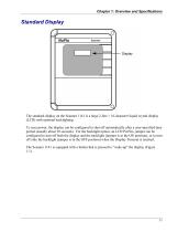
Chapter 1: Overview and Specifications Standard Display The standard display on the Scanner 1141 is a large 2-line × 16-character liquid crystal display (LCD) with optional backlighting. To save power, the display can be configured to shut off automatically after a user-specified time period (usually about 30 seconds). For the backlight option, an LCD PwrSav jumper can be configured to turn off both the display and the backlight (jumper is in the ON position), or to turn off only the backlight (jumper is in the OFF position) when the Display Timeout is reached. The Scanner 1141 is equipped with...
Open the catalog to page 11
Scanner 1141 Hardware User Manual Figure 1.1—Display “wake-up” button Auto-scroll The display “auto-scrolls” through a list of user-definable readouts. Each item is held on the display for a configurable amount of time and is then replaced by the next item in the list. An operator can pause the auto-scroll on any displayed item by pressing the “wake-up” button. The following is a sample of an auto-scroll screen: Run 1 Pf On 492.00000 PSI While in auto-scroll, the following unit status screen is displayed each time the Scanner completes a loop through the list: Time= 09:00 ML Date= Ja
Open the catalog to page 12
Chapter 1: Overview and Specifications The display will shut off automatically after a configurable amount of time (usually about 30 seconds). To “wake-up” the display, press the “wake-up” button. Scanner Software ScanWin Lite is a Windows™-based software program for monitoring, configuring and downloading Scanner Measurement RTU data on-site. ScanWin Lite’s “wizards” guide the operator through the setup of hardware, flow runs, and primary devices as well as the collection of hardware, system, and flow run data. Reports can be exported and printed from ScanWin. ScanWin Lite also facilitates the...
Open the catalog to page 13
Scanner 1141 Hardware User Manual • GERG Virial Equation for Field Use Standard GERG Virial Equation NFlo NFLo performs the same calculations as NGas, plus liquid properties calculations based on the API Manual of Petroleum Measurement Standards (MPMS) chapters 11.2.1, 11.2.2, 11.2.3 and API 2540. Audit Trail The Scanner 1141 maintains a detailed audit history of all configuration records, user changes and system alarms. It also maintains a history of events including hourly and daily flow history. The Event log operates as a circular buffer that contains 100 typical events. Each new event added...
Open the catalog to page 14
Chapter 3: Main Circuit Board Wiring CAUTION ALWAYS TURN OFF POWER TO THE SCANNER 1141 BEFORE REMOVING ANY ELECTRONIC CIRCUIT BOARDS. FAILURE TO DO SO CAN DAMAGE THE SCANNER. CIRCUIT BOARDS ARE SUBJECT TO DAMAGE IF EXPOSED TO STATIC ELECTRICITY. CAUTION CIRCUIT BOARDS MUST BE HANDLED AND INSTALLED IN AN ENVIRONMENT FREE OF STATIC ELECTRICITY AND THE OPERATOR MUST BE GROUNDED. WHEN REMOVING CIRCUIT BOARDS FROM THE SCANNER 1141, ALWAYS PLACE THEM IN PROTECTIVE CONDUCTIVE ENVELOPES. NEVER SUBJECT THE RTU TO AMBIENT OR OPERATING TEMPERATURES BEYOND -40°C to +60°C (-40°F to +140°F). FOR ADDITIONAL...
Open the catalog to page 15All CAMERON catalogs and technical brochures
 BARTON
3 Pages
 Scanner 1140
132 Pages
 PULSE
PULSE20 Pages
 H2
H216 Pages
 Control Chokes
16 Pages
 CAM30-DC
1 Page
 CAMERON T30 Series
2 Pages
 L series
84 Pages
 CAM series
12 Pages
 Multiple Orifice Valve Chokes
30 Pages
 CC series
16 Pages
 T30
T302 Pages
 LEFM® 880 Flow Meter
2 Pages
 Choke and Kill Manifold Systems
12 Pages
 Drilling Product Overview
84 Pages
 Surface System Technology
78 Pages
 Multitrim Choke Valves Brochure
12 Pages


Archived catalogs
 Metering Systems Solutions
10 Pages
 Mud Flow Sensor
1 Page
 Scanner 1131
176 Pages


