Scanner 1140
1 /132Pages

Scanner 1140
1 /132Pages
Catalog excerpts

Scanner 1140 RTU Hardware User Manual
Open the catalog to page 1
© 2010 Cameron International Corporation (“Cameron”). All information contained in this publication is confidential and proprietary property of Cameron. Any reproduction or use of these instructions, drawings, or photographs without the express written permission of an officer of Cameron is forbidden. All Rights Reserved. Printed in the United States of America. Manual No. 9A-30165006, Rev. 02 August 20
Open the catalog to page 2
Warranty The Company warrants all products of its manufacture and bearing its nameplate for a period of one year after date of shipment from its factory to be free from defects in material and workmanship subject to the following: The Company’s liability under this warranty is limited, in the sole and absolute discretion of the Company, to refunding the purchase price, to repairing, or to replacing parts shown to the satisfaction of the Company to have been defective when shipped and then only if such defective parts are promptly delivered to its factory, transportation charges prepaid. This...
Open the catalog to page 3
Product Warranty Statement The warranty applicable to this product is stated at the beginning of this manual. Should any problem arise after-delivery, please contact Cameron’s Measurement Systems Division HelpDesk at 1-877-805-7226 or the Customer Service department during normal business hours at (403) 291-4814. Before installing the instrument, become familiar with the installation instructions presented in this document. Also, be aware of the following important notices that appear throughout the manual: WARNING notes indicate the presence of a hazard that can cause severe personal injury,...
Open the catalog to page 4
Introduction Overview of the Scanner 1140 The Scanner® 1140 is an economical, single stream measurement Remote Terminal Unit (RTU) with flow and pressure control capability. It offers a powerful alternative to chart recorders in gathering data for natural gas production and includes a full range of operator selectable mass, energy and volume algorithms. Cameron’s Barton DPE+ Multi-Variable Transducer (MVT) mounts directly to the Scanner 1140 to provide accurate, low cost measurement for both static and differential pressures in a single device. The 1140 can also use the MVX® or MVX®-II multi-variable...
Open the catalog to page 9
Scanner 1140 Hardware User Manual Scanners 1140T, 1140C, 1140L, and 1140G The Scanner 1140T, often referred to as the standard Scanner 1140 unit, is a 6Vdc EFM rated for Class I, Div.1 Intrinsically Safe applications. The device has no integral communications. It is housed in a fiberglassreinforced plastic enclosure. All Class I, Division 1 installations require an intrinsically safe barrier adapter (Part No. 9A-30058901) between the Scanner and the DPE+ transducer. The adapter is not required for Class I, Division 2 installations. The Scanner 1140C has the same main board as the Scanner 1140T...
Open the catalog to page 10
CAUTION POWER TO THE SCANNER 1140 MUST BE TURNED OFF PRIOR TO THE REMOVAL OF ANY ELECTRONIC CIRCUIT BOARDS OR DAMAGE TO THE SCANNER MAY RESULT. CIRCUIT BOARDS ARE SUBJECT TO DAMAGE IF EXPOSED TO STATIC ELECTRICITY. HANDLING AND INSTALLING CIRCUIT BOARDS MUST BE PERFORMED IN AN ENVIRONMENT FREE OF STATIC ELECTRICITY AND THE OPERATOR MUST BE GROUNDED. WHEN CIRCUIT BOARDS ARE REMOVED FROM THE SCANNER 1140, THEY MUST BE PLACED IN PROTECTIVE CONDUCTIVE ENVELOPES. Note: Circuit boards returned to Cameron’s Measurement Systems Division factory for repair must be properly packed for static protection...
Open the catalog to page 11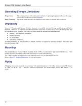
Scanner 1140 Hardware User Manual Operating/Storage Limitations Temperature: Static Electricity: The instrument is not to be subjected to ambient or operating temperatures beyond the range listed in the specification section (Page 85). The circuit boards are not to be subjected to any source of external static electricity. Unpacking Cameron’s Measurement Systems Division Scanners are carefully inspected during manufacturing and before shipment. However, an inspection should be performed at the time of unpacking to detect any damage that may have occurred during shipment. The following items should...
Open the catalog to page 12
Typical Installation of Scanner 1140T Class I, Division 1, Groups C & D Intrinsically safe or Class I, Division 2, Groups A, B, C & D non-sparking
Open the catalog to page 13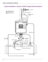
Scanner 1140 Hardware User Manual Typical Installation - Scanner 1140C/L Integral Communications
Open the catalog to page 14
Typical Installation (with Remote Communications)
Open the catalog to page 15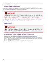
Scanner 1140 Hardware User Manual Power Supply Connection Conduit entry is provided on the right-hand side of the enclosure for the power supply/solar panel wires (refer to Page 97 - Outline Dimensions for size and location of conduit entry. WARNING ALL METALLIC CONDUIT CONNECTORS MUST BE GROUNDED TO THE INTERNAL GROUND WITH THE SHORTEST WIRE POSSIBLE. Also, check Page 31 – (Main Board and Wiring) for additional wiring information. Installation Drawings for information about installation in a Hazardous Location. Power Supply WARNING THE BATTERY IS USER-CHANGEABLE. HOWEVER, IT MUST BE REPLACED...
Open the catalog to page 16
Chapter 1: Installation Scanner Enclosure Solar Panel Wiring Connection Protective Battery Cover Warning Label Slot Local Communication Port Scanner 1140T (With Battery Cover Removed)
Open the catalog to page 17
Scanner 1140 Hardware User Manual 12-Volt Battery Power Supply, Division 2 Controller The following configurations of the 1140 are suitable for Class I, Division 2 when installed as per Appendix A: Installation Drawings 9A-1140-11012). Scanner 1140C (Front View with Door Open)
Open the catalog to page 18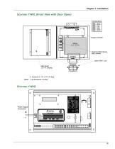
Scanner 1140L (Front View with Door Open)
Open the catalog to page 19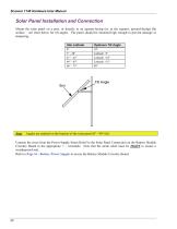
Scanner 1140 Hardware User Manual Solar Panel Installation and Connection Mount the solar panel on a post, or directly to an equator-facing (or, at the equator, upward-facing) flat surface – see chart below for tilt angles. The panel should be mounted high enough to prevent damage or tampering. Site Latitude 0° 5° - 20° 21° - 45° 46° - 65° 66° - 75° Optimum Tilt Angle 10° Latitude +5° Latitude +10° Latitude +15° 80° Tilt Angle Angles are marked on the bracket of the solar panel (0° - 90° tilt) Connect the wires from the Power Supply Strain Relief to the Solar Panel Connection on the Battery Module...
Open the catalog to page 20All CAMERON catalogs and technical brochures
 BARTON
3 Pages
 Scanner 1141
120 Pages
 PULSE
PULSE20 Pages
 H2
H216 Pages
 Control Chokes
16 Pages
 CAM30-DC
1 Page
 CAMERON T30 Series
2 Pages
 L series
84 Pages
 CAM series
12 Pages
 Multiple Orifice Valve Chokes
30 Pages
 CC series
16 Pages
 T30
T302 Pages
 LEFM® 880 Flow Meter
2 Pages
 Choke and Kill Manifold Systems
12 Pages
 Drilling Product Overview
84 Pages
 Surface System Technology
78 Pages
 Multitrim Choke Valves Brochure
12 Pages


Archived catalogs
 Metering Systems Solutions
10 Pages
 Mud Flow Sensor
1 Page
 Scanner 1131
176 Pages


