Scanner 1131
1 /176Pages

Scanner 1131
1 /176Pages
Catalog excerpts

Scanner 1131 Measurement RTU Hardware Manual Above: Scanner 1131 rack-mount Right: Scanner 1131S with dual DPE+ units
Open the catalog to page 1
WARRANTY The Company warrants all products of its manufacture and bearing its nameplate for a period of one year after date of shipment from its factory to be free from defects in material and workmanship subject to the following: The Company’s liability under this warranty is limited in the sole and absolute discretion of the Company to refunding the purchase price, to repairing, or to replacing parts shown to the satisfaction of the Company to have been defective when shipped and then only if such defective parts are promptly delivered to its factory, transportation charges prepaid. This warranty...
Open the catalog to page 2
Any use or application that deviates from the stated performance specification is not recommended and could render the instrument unsafe. The Company should be advised of any apparent deviation or deficiency from specifications including safety related deficiencies, at the above factory address, to the attention of the Marketing Department. A return authorization will be issued, where applicable, for goods returned for inspection, calibration or repair, under warranty. PRODUCT WARRANTY STATEMENT The warranty applicable to this product is stated at the beginning of this manual. Should any problem...
Open the catalog to page 3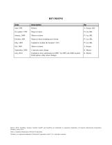
REVISIONS Date Major revision Minor revisions Major revision including new format Updated to include the Scanner 1131C Minor revisions Corporate name change Updated to show substitution of DPE+ for DPE cell, EB02 modem board option; other minor changes Barton, MVX, ScanBase, Scanner, ScanOp, ScanPC and ScanWin are trademarks or registered trademarks of Cameron International Corporation, Houston, Texas, USA. Intel is a registered trademark of the Intel Corporation. Windows is a registered trademark of Microsoft Corporation in the U.S.A. and other countries.
Open the catalog to page 4
Scanner 1131 Hardware Manual
Open the catalog to page 6
Scanner 1131 Hardware Manual
Open the catalog to page 8
Scanner 1131 Hardware Manual
Open the catalog to page 10
Introduction Overview The Scanner® 1131 is an intrinsically safe solar-charged, battery-powered, weatherproof flow computer that calculates flow for two or more meter runs using standard algorithms. It is housed in a metal or plastic enclosure that can be wall or pipe mounted. It is also available in a rack mount style. The Scanner 1131 provides compatibility between the existing Scanner 1130 enclosure, Scanner 1140 style DPE® units, and 1130 expansion boards. This provides a logical board replacement upgrade path from the Scanner 1130 to the 1131, as numerous enhancements over the 1130 have...
Open the catalog to page 11
Scanner 1131 Hardware Manual A variety of software programs are available for configuring, monitoring, downloading, retrieving data, reading and creating reports from collected data: ScanWin™ - ScanWin is a Windows™-based software program that is used to monitor, configure, and download Device Measurement RTU data on-site. Data is displayed graphically and in tables. Reports can also be printed from ScanWin. ScanPC™ - ScanPC™ is a DOS-based software program for a PC that is used to monitor, configure, and download Scanner data on-site. Scanner files can be printed in a universal report format...
Open the catalog to page 12
1: Installation Installing the Scanner 1131 CAUTION POWER TO THE SCANNER 1131 MUST BE TURNED OFF PRIOR TO THE REMOVAL OF ANY ELECTRONIC CIRCUIT BOARDS OR DAMAGE TO THE SCANNER MAY RESULT. CIRCUIT BOARDS ARE SUBJECT TO DAMAGE IF EXPOSED TO STATIC ELECTRICITY. HANDLING AND INSTALLATION OF CIRCUIT BOARDS MUST BE PERFORMED IN AN ENVIRONMENT FREE OF STATIC ELECTRICITY AND THE OPERATOR MUST BE GROUNDED. WHEN CIRCUIT BOARDS ARE REMOVED FROM THE SCANNER 1131, THEY MUST BE PLACED IN PROTECTIVE CONDUCTIVE ENVELOPES. Circuit boards returned to Cameron’s Measurement Systems Division factory for repair must...
Open the catalog to page 13
Scanner 1131 Hardware Manual Operating/Storage Limitations Temperature The instrument is not to be subjected to ambient or operating temperatures beyond the range listed in the specifications. Static Electricity The circuit boards are not to be subjected to any source of external static electricity. Unpacking Cameron’s Measurement Systems Division Scanners are carefully inspected during manufacturing and before shipment. However, an inspection should be performed at the time of unpacking to detect any damage that may have occurred during shipment. The following items should be included with each...
Open the catalog to page 14
Power Supply Class I, Div. 1 Battery Charger / Power Supply The Class I, Div. 1 battery charger and power supply is designed to charge a 12 V lead acid battery and provide the necessary power to operate the Scanner 1131. (Intrinsically Safe, Class I, Div. 1, Groups C and D, when installed as per APPENDIX A: Drawings) WARNING PLEASE HEED THE WARNING LABEL ON THE BATTERY BRACKET. BE SURE TO REPLACE THE BATTERY IN A NON-HAZARDOUS AREA, OTHERWISE THERE IS A RISK OF SEVERE PERSONAL INJURY, DEATH, AND SERIOUS PROPERTY DAMAGE. CAUTION PLEASE OBSERVE THE CAUTIONARY NOTE ON THE WARNING LABEL OF THE BATTERY...
Open the catalog to page 15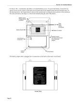
Scanner 1131 Hardware Manual In Class I, Div. 1 instruments, the battery is located behind a cover. To access the battery, loosen the two captive screws at the corners of the main circuit board and tilt the hinged board forward (towards user). In the drawing below, the hinged board is shown fully opened and covering the lower portion of the enclosure. On some enclosures, the hinge is vertical and oriented along the side of the board. Battery Circuit Charge Module (invisible) Battery Bracket Solar Panel Wiring Connection Caution: Do Not Ship Scanner With Battery Module Inside. Doing So Will Damage...
Open the catalog to page 16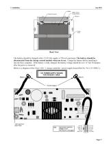
July 2010 Battery Positive Terminal Battery Circuit Charge Module Bracket Velcro Strap Back View The battery should be charged with a 15-28 Vdc supply at 750 mA maximum. The battery should be disconnected from the charge control module when not in use. Charge the battery before installing it into the flow computer. If the battery is fully charged, the battery voltage should be over 13 Vdc 30 minutes after the power is removed. Below is a diagram of the Class I, Div. 1 charge controller / power supply board (Part No. 9A-1131-0301C).
Open the catalog to page 17All CAMERON catalogs and technical brochures
 BARTON
3 Pages
 Scanner 1140
132 Pages
 Scanner 1141
120 Pages
 PULSE
PULSE20 Pages
 H2
H216 Pages
 Control Chokes
16 Pages
 CAM30-DC
1 Page
 CAMERON T30 Series
2 Pages
 L series
84 Pages
 CAM series
12 Pages
 Multiple Orifice Valve Chokes
30 Pages
 CC series
16 Pages
 T30
T302 Pages
 LEFM® 880 Flow Meter
2 Pages
 Choke and Kill Manifold Systems
12 Pages
 Drilling Product Overview
84 Pages
 Surface System Technology
78 Pages
 Multitrim Choke Valves Brochure
12 Pages


Archived catalogs
 Metering Systems Solutions
10 Pages
 Mud Flow Sensor
1 Page


