
- Catalogs
- Cambridge Technology
- PHCAB Outline Drawing

PHCAB Outline Drawing

PHCAB Outline Drawing
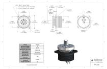
Technical Drawing Dimensions and Specifications Summary
This document provides detailed mechanical dimensions and specifications for a component or assembly, including measurements in both inches and millimeters. The key dimensions are as follows:
- Overall lengths and widths range from approximately 4.200 inches (106.68 mm) to 6.500 inches (165.10 mm).
- Multiple hole sizes and placements are specified, including four through holes of 0.281 inches (7.14 mm) diameter.
- Additional holes of 0.31 inches (7.87 mm) diameter are positioned at 90° angles on both near and far sides.
- Other critical dimensions include 4.450 inches (113.03 mm), 1.234 inches (31.34 mm), 2.145 inches (54.48 mm), 3.608 inches (91.63 mm), and 2.920 inches (74.17 mm).
- Smaller features such as 0.200 inches (5.08 mm), 1.067 inches (27.09 mm), 0.823 inches (20.90 mm), and 0.950 inches (24.13 mm) are also noted.
Additional Notes and Features:
- There is an optional encoder mount and a mirror mount indicated, suggesting modularity or optional components.
- An air inlet is specified as 5/32 inch (4 mm), indicating pneumatic or airflow considerations.
- The drawing includes a labeling scheme with letters (A, B, C, D) and numbers (1 through 8), possibly for pin or connector identification.
- The document is dated March 28, 2018, and includes a disclaimer that all specifications are subject to change without notice.
Critical Parameters and Recommendations:
- Ensure hole diameters and placements are precisely followed to maintain assembly integrity.
- Optional components such as the encoder and mirror mounts should be installed according to application requirements.
- Air inlet sizing must be adhered to for proper pneumatic function.
- Connector or pin labeling should be cross-referenced with electrical or control schematics for correct wiring.
This summary captures the essential mechanical and functional specifications necessary for manufacturing, assembly, and integration of the component described.
Catalog excerpts
"ALL SPECIFICATIONS SUBJECT TO CHANGE WITHOUT NOTICE" ENCODER OPTIONAL CAMBRIDGE TECHNOLOGY A Novanta Company
Open the catalog to page 1All Cambridge Technology catalogs and technical brochures
 Diode Pointer
2 Pages
 ScanMaster Designer
2 Pages
 POLYGONAL MIRRORS
4 Pages
 Lincoln hyperSCAN Series
3 Pages
 SA24 Outline Drawing
1 Page
 SA24C Outline Drawing
1 Page
 P1AB Outline Drawing
1 Page
 LXP Hybrid
5 Pages
 ProSeries 2
4 Pages
 ProSeries Scan Head
5 Pages
 3-Axis Scan Head
2 Pages
 ScanMaster Controller
4 Pages
 CRS Series
3 Pages
 NEW LII/ScanMaster Brochure
2 Pages
 Pen Motors
3 Pages
 Rotary Actuators
3 Pages
 Scanning Components Brochure
4 Pages
 ScanMaster? Brochure
4 Pages
 3-Axis Brochure
4 Pages
 Scan Heads Brochure
4 Pages
 Scan Head Solutions
4 Pages
 Optical Scanning Components
6 Pages


- Power supply unit
- DC power supply
- AC/DC power supply
- Automation software solution
- Process software
- Windows software
- Computer-aided design software
- Control software
- Design software solution
- Switched-mode power supply
- 3D software solution
- Industrial software
- Servo-amplifier
- Interface software
- DC servo-amplifier
- Regulated power supply
- Pulsed laser
- 3D scanning system
- Solid-state laser
- Laser scanner