- Catalogs
- Cambridge Technology
- Diode Pointer
Diode Pointer
1 /2Pages

Diode Pointer
1 /2Pages
Catalog excerpts

Diode Pointer Technical Data Diode Pointer Emits a visible red laser for convenient laser beam alignment. LASER RADIATION - AVOID DIRECT EYE EXPOSURE LASER DIODE Eliminates cumbersome IR viewing instruments such as thermal image plates and ultraviolet lights. • Emits a visible red laser to serve as an accurate alignment tool when co-aligned with a CO2 laser • Easily mounts to the faceplate of any Synrad CO2 laser 100 watts and below • Easy 4-step installation process, and 5-step alignment process • Adjustable for establishing far-field and near-field coincidence between the CO2 laser and the diode beams • Near-field distance ~ 30 cm; far-field distance ~ 3 - 10 m. • Added safety benefit - enables the user to clearly monitor the location of the laser beam Max. Output: 5 mW CLASS IIIA LASER PRODUCT Note - Copper case not grounded. Reverse polarity protected. Beam Delivery Set-Up The Diode Pointer, when properly mounted to the laser, produces a beam centerline shift of 1 mm from its original exiting point on the laser. The direction of this offset is dependent upon the orientation of the Diode Pointer to the laser (see reverse side). The CO2 laser beam leaving the Diode Pointer is centered to the exiting bore of the pointer, however the beam centerline itself has shifted in relation to any beam delivery components not directly mounted on the pointer. Make necessary adjustments to your beam delivery setup in order to compensate for this 1 mm offset. When mounting components directly to the Diode Pointer, the CO2 laser beam is centered and no additional adjustments are required. SYNRAD A Novanta Company Quick adjustment for far-field and near-field make alignment fast and easy. Make fine adjustments to the diode beam by manually adjusting screws the appropriate screws for either far-field or near-field. Recommended near field distance is approximately 30 cm, and far-field distance is 3 - 10 meters. Take adequate safety precautions to restrict access to the area where the CO2 laser beam will be projected. Ensure that all necessary laser safety precautions are taken to avoid injuries to persons and ignition of combustible items by the invisible CO2 laser beam.
Open the catalog to page 1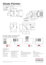
Technical Illustrations dimensions are in inches Direction of beam centerline shift for Diode Pointer orientations Beam Direction Beam Direction Beam Direction Contact Us synrad.com Americas & Asia Pacific Synrad 4600 Campus Place Mukilteo, WA 98275 P (425) 349.3500 F (425) 349.3667 [email protected] Europe, Middle East, Africa Novanta Europe GmbH Division Synrad Europe Parkring 57-59 D-85748, Garching, Germany P +49 (0)89 31707 0 F +49 (0)89 31707 222 [email protected] China Synrad China Sales and Service Center Unit C, 5/F, Ting Wei Industrial Park Liufang Road, Baoan District, Shenzhen...
Open the catalog to page 2All Cambridge Technology catalogs and technical brochures
 ScanMaster Designer
2 Pages
 POLYGONAL MIRRORS
4 Pages
 Lincoln hyperSCAN Series
3 Pages
 PHCAB Outline Drawing
1 Page
 SA24 Outline Drawing
1 Page
 SA24C Outline Drawing
1 Page
 P1AB Outline Drawing
1 Page
 LXP Hybrid
5 Pages
 ProSeries 2
4 Pages
 ProSeries Scan Head
5 Pages
 3-Axis Scan Head
2 Pages
 ScanMaster Controller
4 Pages
 CRS Series
3 Pages
 NEW LII/ScanMaster Brochure
2 Pages
 Pen Motors
3 Pages
 Rotary Actuators
3 Pages
 Scanning Components Brochure
4 Pages
 ScanMaster? Brochure
4 Pages
 3-Axis Brochure
4 Pages
 Scan Heads Brochure
4 Pages
 Scan Head Solutions
4 Pages
 Optical Scanning Components
6 Pages


- Power supply unit
- DC power supply
- AC/DC power supply
- Automation software solution
- Process software
- Windows software
- Computer-aided design software
- Control software
- Switching power supply
- Design software solution
- 3D software solution
- Industrial software
- Interface software
- Servo-amplifier
- DC servo-amplifier
- Pulsed laser
- Regulated power supply
- 3D scanning system
- Solid-state laser
- Laser scanner