

Ferrite Magnets

Ferrite Magnets
Overview of Ferrite Magnets
Ferrite magnets, patented in 1952, are widely used due to their excellent cost-to-performance ratio. They consist mainly of iron oxide combined with barium or strontium carbonate and are manufactured through dry or wet sintering. While standard size tables exist, customized dimensions are recommended for optimal application fit, with adaptable molds often available.
Standard Tolerances
- Length and width: ±2%
- Thickness: ±0.1 mm
Dimensional Specifications
Detailed dimensional tables cover various ferrite magnet types (SXD, SXM, SXP, SXF, SXX, USF) with measurements in millimeters. Sizes smaller than 152 x 101 x 25.4 mm can be produced for certain types (Art. 375).
Material Types and Magnetic Properties
Ferrite magnets are categorized as isotropic or anisotropic:
- Isotropic (SXD): No preferred magnetization direction; composition approx. 80% Fe2O3 and 19% BaCO3; hardness 8 Vickers.
- Anisotropic (SXM, SXP, SXX, USF): Preferential magnetization direction; composition approx. 94.24% Fe2O3 and 9.76% SrO.
Key magnetic parameters include residual induction (BR), coercive field (Hc), maximum energy product (BH max), and specific weight. For example, anisotropic wet ferrites (SXP) exhibit BR values of 3800-4000 Gauss, coercive fields of 2800-3000 Oersted, and minimum max energy products of 2800 kJ/m³.
Additional Characteristics
- Curie temperature: 450-460 °C
- Maximum recommended working temperature: 250-280 °C
- Temperature coefficient of BR: -0.18 to -0.20 % per °C
- Electrical resistivity: 104 to 108 Ω·cm
Manufacturing and Magnetization Processes
Production employs computerized automatic cutting machines with precision up to ±0.02 mm, along with tangential and centerless grinding for rapid fabrication of any magnet shape. Capacitive discharge magnetizers ensure consistent, balanced magnetization tailored to the final application.
Magnetic Circuit and Force Enhancement
Tractive force depends on magnet volume, material type, and magnetization direction. Incorporating simple soft iron circuiting can significantly increase force. Tests show that axially magnetized anisotropic ferrite magnets circuitized with two soft iron laminations can achieve contact forces up to 18 times greater than uncircuitized magnets.
Calculation of Tractive Force
The L/D ratio (thickness divided by diameter) and provided graphs enable calculation of contact tractive force for isotropic and anisotropic ferrite magnets. For example, a 12 mm diameter, 6 mm thick anisotropic ferrite disk has an area of approximately 1.1304 cm² and an L/D ratio of 0.5, corresponding to a force density of 3.1 N/cm². Multiplying area by force density yields a tractive force of about 3.5 N, with a ±12% tolerance depending on magnet grade.
For parallelepiped shapes, diameter is replaced by the formula D = (side × 4) / π. Graphs also illustrate how increasing airgap reduces tractive force significantly.
Summary of Critical Parameters and Best Practices
- Request customized dimensions for optimal fit.
- Use anisotropic ferrite magnets for superior magnetic performance.
- Employ magnetic circuiting with soft iron to maximize tractive force.
- Utilize precise manufacturing and magnetization techniques to ensure quality and consistency.
- Calculate tractive force using L/D ratio and area, applying ±12% tolerance.
- Observe maximum working temperatures and temperature coefficients to maintain magnet performance.
Calculation of Traction Force for Anisotropic Ferrite Magnets
This section details the method to calculate traction force for anisotropic ferrite magnets, especially for axial magnetization through thickness.
Key Parameters and Formulas
- Area Calculation: For disk magnets, area = (Radius² × π) / 100, yielding cm².
- L/D Ratio: Thickness (L) divided by diameter (D) is critical for force estimation.
- Diameter Replacement for Parallelepipeds: Use D = (side × 4) / π instead of diameter.
Example Calculation
- Disk diameter: 12 mm; thickness: 6 mm
- Area: 1.1304 cm²
- L/D ratio: 0.5
- Force density from graphs: 3.1 N/cm²
- Calculated traction force: 3.5 N (±12% tolerance)
Effect of Airgap on Traction Force
Airgap variations significantly impact traction force, as shown in color-coded diagrams (Yellow: figure E, Red: figure C, Blue: figure A). Tests on a 45 mm diameter, 8.5 mm thick anisotropic ferrite disk confirm this effect.
Graphical Data Summary
Graphs illustrate traction force versus airgap for isotropic and anisotropic ferrite magnets, showing force decreases with increasing airgap. Another graph relates L/D ratio to traction force density, highlighting higher adhesion for anisotropic ferrite.
Adhesion Factors
- Range from 1 to 18 depending on magnet type and conditions.
- These factors influence effective traction force and should be integrated into design considerations.
Critical Notes and Recommendations
- Use L/D ratio and area for accurate traction force estimation.
- Apply ±12% tolerance for anisotropic ferrite magnets.
- Adjust calculations for parallelepiped shapes using the diameter substitution formula.
- Carefully consider airgap effects due to their significant impact on force.
- Refer to color-coded diagrams for detailed traction force variations with airgap.
Catalog excerpts
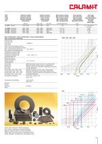
TIPOInduzione residuaCampo coercitivoMax prodotto energiaPeso specificoAltre sigleTIPOInduccin residuaCampo coercitivoMx producto energ㡭aPeso especficoOtras siglas TYPEResidual inductionCoercive fieldMax energy productSpecific weightOther abbreviationsTYPEInduction rsiduelleChamp coercitifMax. produit nergiePoids spcifiqueAutre sigleTYPRestinduktionKoerzitivfeldMax. EnergieproduktSpezyfische GewichtSonstigeAbkrzungen BR (G)BHC (OE)IHC (OE)BH MAX (MG OE)g/cm > 3 Dry SXD isotropo2100 / 23001850 / 195032001,054,5y 10 - Ferroxdure I Oxit 100 Wet SXM anisotropo3500 / 39001900 / 26002000 (Min)2,8 /...
Open the catalog to page 2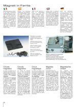
Calamit in der Lage,innerhalb kurzer Zeit jedes beliebige Format herzustel- len. Die Magnetisiervorrichtungen mit kapazitiver Entladung erlauben neben der Gewhrleistung einer gleich- bleibenden und ausgegliche- nen Leistung eine Magnetisierung in der je nach Endverwendung geeignet- sten Form und Richtung. Calamit is able to obtain any format in short time. The capacitive discharge magnetizing devi- ces allow to magnetize in the most suitable form and direc- tion, according to the final use, assuring a costant and balanced efficiency as well. Dank der exklusiven, rechnergesteuerten Schneideautomaten...
Open the catalog to page 3All CALAMIT catalogs and technical brochures
 Teaching-magnets
1 Page
 Blackboards
1 Page
 Ferromagnetic Paper
1 Page
 Bonded Ferrite e Sam/Co
2 Pages
 Laminated plastic
2 Pages
 Plastic extruded
2 Pages
 Neodymium Magnets Rare Earth
4 Pages
 Coaniax cast
3 Pages
 Magnetic Circuit
2 Pages