

Screw-clamp terminal blocks - Polyamide insulated

Screw-clamp terminal blocks - Polyamide insulated
The document provides comprehensive specifications and features of various series of screw-clamp terminal blocks, including CBC, CBR, GPA, TEC, CBD, GPM, ACB, and MBL series. These terminal blocks are polyamide insulated and designed for feed-through and high-current applications. Key features include the use of UL94V-0 polyamide for insulation, reduced dimensions, and the patented 'Easy Bridge' system for cross-connections without additional insulation protection. They are compatible with PR/3 type rails as per IEC 60715 standards and are available in grey and beige colors.
The Easy Bridge System allows for versatile cross-connection configurations, including single or parallel, extending, pole skipping, adjacent with or without barriers, and staggered modes. The system supports cross-connections in standard sizes or custom lengths, ensuring full insulation and IPXXB protection.
The CBC series terminal blocks are available in various configurations with different rated cross-sections (2.5 mm² to 50 mm²) and rated voltages (up to 1000 V). They support flexible and rigid connections and have specific tightening torque values. The series is certified with CESI 08 ATEX 061 U Ex e and CoC IEC Ex N. CES 09.0002U Ex e II, suitable for operating temperatures from -40 to +80°C.
The document lists various accessories such as end sections, cross-connections, test plugs, and mounting rails. It also mentions approvals and certifications for different series, ensuring compliance with international standards.
Each series has detailed technical characteristics, including rated voltage, current, insulation stripping length, and dimensions. The document provides configurations for PTC jumpers and cross-connections, highlighting their insulation voltage capacities and compatibility with different terminal block sizes.
The document provides detailed technical specifications and characteristics of various terminal blocks and accessories, including feed-through, power, and earth terminal blocks. It covers different models, their technical parameters, approvals, and available accessories.
- G32 and TH/35 Types: Available in grey (RAL 7042) and beige (RAL 1001). They feature a feed-through function with a rated cross-section of 2.5 mm² and a rated voltage of 800 V / 24 A. The insulation stripping length is specified for both upper and lower sections.
- GPA Series Power Terminal Blocks: These blocks are designed for mounting on PR/DIN and PR/3 type rails. They support high current capacities and are available in both grey and beige colors. The rated cross-section ranges from 70 mm² to 240 mm², with rated voltages up to 1000 V.
- Earth Terminal Blocks: Designed for mounting on PR/3 and PR/DIN rails, these blocks are available in green/yellow insulating cases. They support cross-sections from 6 mm² to 71 mm² and are pending various approvals.
- Each terminal block type is detailed with its rated cross-section, connecting capacity, rated voltage/current, insulation stripping length, and tightening torque values.
- Specifications conform to IEC 60947-7-1 and UL standards, ensuring compatibility and safety.
- Various accessories are available, including end sections, cross connections, shunting screws, test plugs, and mounting rails. These accessories enhance the functionality and flexibility of the terminal blocks.
- Marking tags and end brackets are provided for easy identification and secure mounting.
- Many of the terminal blocks and accessories are pending approvals from UL, cUL, ATEX Ex e, and IEC Ex, ensuring compliance with international safety standards.
- The document highlights the compact design, high connecting capacity, and low contact resistance of the terminal blocks, emphasizing their reliability and practical usage.
- It also mentions the use of high-quality materials for maximum reliability over time.
The document provides detailed technical specifications and features of the CBD Series screw-clamp feed-through terminal blocks with a polyamide insulating body. These terminal blocks are designed for universal mounting onto PR/DIN and PR/3 type rails according to IEC 60715 standards and are suitable for use in potentially explosive environments.
- Material: UL94V-0 flame-retardant polyamide.
- Mounting: Compatible with "G32" and "TH/35" rails.
- Temperature Range: -40 to +80 °C.
- Rated Voltage/Current: Up to 800 V and 125 A depending on the model.
- Approvals: CESI ATEX, CoC IEC Ex, UL (U.S.A.-Canada).
- Flexible conductors: Varies by model, up to 50 mm².
- Rigid conductors: Varies by model, up to 50 mm².
- Ease of Insertion: Sloping entrance planes and rounded edges facilitate conductor insertion.
- Tightening Mechanism: Screw-based, ensuring reliable mechanical performance and electrical contact.
- Additional Functions: Cross-connection capabilities, test plug insertion, and marking options.
- End sections, cross connections, test plugs, and marking tags are available for customization and functionality enhancement.
These terminal blocks are suitable for various industrial applications, especially where safety and reliability in electrical connections are critical, including environments with explosion risks.
The document provides detailed technical specifications for various high current terminal blocks, specifically the D.50 (Ex)i and CBD.70 (Ex)i models, as well as the GPM series. These terminal blocks are designed for feed-through applications with rated cross-sections ranging from 50 mm² to 240 mm².
The connecting capacity varies by model, with flexible and rigid options available. For example, the D.50 model supports flexible connections from 1.5 to 95 mm² and rigid connections from 1 to 95 mm².
The rated voltage and current are specified according to IEC 60947-7-1 and UL standards. For instance, the D.50 model is rated at 800 V / 150 A according to IEC standards and 600 V / 130 A according to UL standards.
All models have a rated impulse withstand voltage of 8 KV and a pollution degree of 3.
The document details the dimensions for different mounting options, including TH/35 and G32 types, and provides information on the panel-mount versions.
The terminal blocks are pending approvals from UL, cUL, ATEX, and IEC Ex, ensuring compliance with international safety and performance standards.
A variety of accessories are available, including end sections, cross connections, and marking tags. The terminal blocks feature a universal mounting system compatible with PR/DIN and PR/3 type rails, and they are available in beige RAL 1001 color.
The document emphasizes the reliability of connections through screw and nut clamping systems, designed to counteract dynamic stress and vibrations. The insulating bodies provide an IPXXB degree of protection, ensuring safety without additional accessories.
The terminal blocks feature a unique design with articulated insulating bodies and cross grooving on contact surfaces to enhance connection characteristics and mechanical retention.
The document provides detailed technical specifications and features of various terminal blocks and fuse holders used in electrical installations. It includes information on materials, dimensions, electrical ratings, and compatibility with standards.
- Terminal blocks are available in steel and aluminum, with options for different rail types (PR/DIN and PR/3) and configurations (with or without slots).
- Push-on connections conform to IEC 60760 standards, with internal cross connections available.
- Materials include UL94V-0 polyamide for insulating bodies, available in grey (RAL 7042) and beige (RAL 1001).
- Rated cross-section: 2.5 mm², with flexible and rigid connecting capacities ranging from 0.2 to 4 mm².
- Rated voltage/current: 250 V/24 A (IEC 60947-7-1) and 600 V/15 A (UL standards).
- Impulse withstand voltage: 4 KV, pollution degree 3.
- Insulation stripping length: 8 mm, with tightening torque values specified.
- Compliant with IEC 60715 for mounting rails and IEC 60947-7-1 for electrical ratings.
- Various accessories available, including end sections, cross connections, and marking tags.
- Use TLS.2 and TLD.2 terminal blocks for efficient connection of proximity sensors, utilizing the LOCK system for secure connections.
- Ensure proper insulation and polarity identification using PRP/5 colored covers.
- Designed for ø 5 x 20 mm and ø 6.3 x 32 mm fuses, with LED indicators for fuse status.
- Available in standard grey and beige colors, with universal mounting options.
1. Current and Voltage Ratings: The document specifies configurations according to IEC 60947-7-1, with rated voltages ranging from 300V to 800V and rated currents from 6.3A to 32A. The configurations include various AWG sizes and tightening torque values.
2. Impulse Withstand Voltage: Rated impulse withstand voltage is specified at 6 KV with a pollution degree of 3.
3. Insulation Stripping Length: The insulation stripping length is consistently 9 to 11 mm across different configurations.
4. Dimensions: The height, width, and thickness vary depending on the mounting rail type (TH/35 or G32), with dimensions provided for each configuration.
1. The document lists various approvals, including LV 27/6 and Distribuzione DV 27/6, among others.
1. End Sections: Available in grey, beige, and blue, with specific catalog numbers for each color.
2. Cross Connections: Permanent and switchable cross connections are available, with specific configurations for different pole numbers.
3. Mounting Rails: Rails are available in steel and aluminum, with options for slots, according to IEC 60715 standards.
1. Insulating Body: Made of UL94V-0 polyamide, available in grey and beige colors.
2. Cross Connections: The document details the ability to perform cross-connections both upstream and downstream of the disconnection point.
3. Slide-Link Disconnect: Allows for special cross-connections and simultaneous earth connections for current transformers.
1. Test Plugs: Sockets for test plugs are available for signal withdrawal.
2. Shunting Screws: Used for short-circuit plates and performing shunting functions.
The document provides detailed technical specifications and configurations for various terminal blocks and diode-holders used in test and measurement circuits. These components are designed for universal mounting on PR/DIN and PR/3 type rails, conforming to IEC 60715 standards.
- Rated Voltages: Available for 5 V dc, 12 V dc, 24 V dc, and 60 V dc for DAS 4/D series; 24 V dc, 48 V dc, 120 V ac, and 230 V ac for DAS 4V series.
- Protection Features: Includes overvoltage protection, pulse jamming protection, and class D protection according to DIN VDE 0675.
- Construction: Made with UL94V-0 polyamide insulating body, available in grey RAL 7042 and beige RAL 1001 colors.
- Devices should be installed as close as possible to the equipment being protected.
- Connection wires must be short, straight, and interwoven with a large cross-section.
- Earth conductors should be short and not parallel to other conductors.
- DAS 4/D Series: Features a 2-level terminal block with a bi-directional suppresser diode, rated for 630 V and 32 A.
- DAS 4V Series: Includes varistors for protection against voltage peaks, with a response time of 20-25 ns and capable of handling discharge currents up to 4500 A.
1. Function/Type: Various terminal blocks with different connection types including feed-through, push-on tab, and screw connections.
2. Rated Cross-Section: Ranges from 2.5 mm² to 4 mm² depending on the model.
3. Rated Voltage/Current: Conforms to IEC 60947-7-1 standards, with voltages up to 800 V and currents up to 20 A.
4. Impulse Withstand Voltage: Up to 8 KV with a pollution degree of 3.
5. Insulation Stripping Length: Varies by model, with some requiring 11 mm.
6. Dimensions: Provided for different mounting standards (TH/35, G32) with specific height, width, and thickness.
Products are pending or have received various approvals, including IEC Ex for certain models.
1. End Sections: Available in grey, beige, and blue.
2. Cross Connections: Permanent and switchable options available, with specific models for different pole numbers.
3. Mounting Rails: Compatible with IEC 60715 standard, available in steel and aluminum.
4. Marking Tags: Printed or blank options for easy identification.
1. Thermocouple Circuits: Terminal blocks designed for thermocouple circuits, allowing direct flow of thermoelectrical e.m.f.
2. Multi-Pole Terminal Boards: Can be mounted independently or overlapped, with special bushings for insulation.
3. Female Connectors: Available in various pole numbers, with secure locking mechanisms.
1. Ensure proper insulation and mounting using specified bushings and end sections.
2. Follow safety guidelines, especially when handling connectors under load.
3. Use appropriate accessories for specific applications to ensure optimal performance and safety.
Catalog excerpts

Screw-clamp terminal blocks Polyamide insulated Feed-through and high-current terminal blocks CBC series . . . . . . . . . . . . . . . . . . . . . . . . . . . . . . CBR.2 . . . . . . . . . . . . . . . . . . . . . . . . . . . . . . . . . GPA series . . . . . . . . . . . . . . . . . . . . . . . . . . . . . . TEC series . . . . . . . . . . . . . . . . . . . . . . . . . . . . . . CBD series. . . . . . . . . . . . . . . . . . . . . . . . . . . . . . GPM series . . . . . . . . . . . . . . . . . . . . . . . . . . . . . ACB series . . . . . . . . . . . . . . . . . . . . . . . . . . . . . . MBL series. . . . . . . . . . . . . . . . . . . . . . . . . . . . . . pages 2-4 page 5 pages 6-7 pages 8-9 pages 10-15 pages 16-19 page 20 pages 21-22 page 23 page 23 page 24 pages 24-25 page 25 Diode-holder terminal blocks SFR.4 . . . . . . . . . . . . . . . . . . . . . . . . . . . . . . . . . page 48 SFR.4/D…. . . . . . . . . . . . . . . . . . . . . . . . . . . . . . page 49 page page page page page page 26 27 28 29 30 31 page page page page page page page page DAS.4/D… series. . . . . . . . . . . . . . . . . . . . . . . . . pages 50-51 DAS.4/V… series. . . . . . . . . . . . . . . . . . . . . . . . . page 52 DAS.4/… series. . . . . . . . . . . . . . . . . . . . . . . . . . page 53 Terminal blocks with special connections and for connectors AFO.2/1+1 - AFO.2/2+2 - AFO.2/2+2/TP. . . . . . . PDF.2 - FDP.2 - CVF.4 . . . . . . . . . . . . . . . . . . . . . CVF.4/…. . . . . . . . . . . . . . . . . . . . . . . . . . . . . . . CF.12/1+1. . . . . . . . . . . . . . . . . . . . . . . . . . . . . . CF.12/2+2. . . . . . . . . . . . . . . . . . . . . . . . . . . . . . TC/PO (for thermocouple circuits) . . . . . . . . . . . . . VPC.2 . . . . . . . . . . . . . . . . . . . . . . . . . . . . . . . . . VPD.2 . . . . . . . . . . . . . . . . . . . . . . . . . . . . . . . . . MAC - CAM system . . . . . . . . . . . . . . . . . . . . . . . Two and three-level terminal blocks DBC.2 - DBC.2/CI. . . . . . . . . . . . . . . . . . . . . . . . . DAS.4 - DAS.4/CI . . . . . . . . . . . . . . . . . . . . . . . . . DAS.4/SS - DSS.4 . . . . . . . . . . . . . . . . . . . . . . . . FVS.4 – FFS.4 . . . . . . . . . . . . . . . . . . . . . . . . . . . TLS.2. . . . . . . . . . . . . . . . . . . . . . . . . . . . . . . . . . TLE.2 - TLD.2 - TDE.2 . . . . . . . . . . . . . . . . . . . . . Serie SCB.6 . . . . . . . . . . . . . . . . . . . . . . . . . . . . . page 46 Serie SCB.10 . . . . . . . . . . . . . . . . . . . . . . . . . . . . page 47 Terminal blocks with electronic components Earth terminal blocks TEO series . . . . . . . . . . . . . . . . . . . . . . . . . . . . . . CBE.2 . . . . . . . . . . . . . . . . . . . . . . . . . . . . . . . . . TED.4 . . . . . . . . . . . . . . . . . . . . . . . . . . . . . . . . . TE/O - TE/D series . . . . . . . . . . . . . . . . . . . . . . . . TTN.35 . . . . . . . . . . . . . . . . . . . . . . . . . . . . . . . . Terminal blocks for test and measurement circuits 32 33 34 35 36 37 38 39 page 54 page 55 page 56 page 57 page 58 page 59 page 60 page 61 pages 62-63 Fuse-holder terminal blocks SFR.4 - SFO.4 - SFR.6/M . . . . . . . . . . . . . . . . . . . SFR.6 - SFR.4/VS - SFO.4/VS . . . . . . . . . . . . . . . . DSF.4/GR . . . . . . . . . . . . . . . . . . . . . . . . . . . . . . MPFA.4 - DSFA.4. . . . . . . . . . . . . . . . . . . . . . . . . CPF/5 component-holder cartridge . . . . . . . . . . . . FPC.10 - FPL.10/C - FPL.10/L . . . . . . . . . . . . . . . SFR.4/C…. . . . . . . . . . . . . . . . . . . . . . . . . . . . . . SFO.4/C…- FPL.10/C… . . . . . . . . . . . . . . . . . . . Mini-terminal blocks RN.1 - RN.2 - RP.4. . . . . . . . . . . . . . . . . . . . . . . . page 64 RFI.2 - TR.2 - TR.4. . . . . . . . . . . . . . . . . . . . . . . . page 65 Multi-pole modular terminal boards BPL – TPL series . . . . . . . . . . . . . . . . . . . . . . . . . pages 66-68 Neutral disconnect terminal blocks CNT series . . . . . . . . . . . . . . . . . . . . . . . . . . . . . . page 69 Disconnect terminal blocks MPS.2/SW - MPS.2/SWP - MPS.2/SV . . . . . . . . . . MPS.4 - MPS.4/VS - DSS.4 . . . . . . . . . . . . . . . . . SFR.4 - SFR.4/VS. . . . . . . . . . . . . . . . . . . . . . . . . SFO.4 - SFO.4/VS - SFR.6/M . . . . . . . . . . . . . . . . SFR.6 - FPC.10 - SCB.4 . . . . . . . . . . . . . . . . . . . . page page page page page 40 41 42 43 44 1
Open the catalog to page 1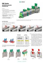
CBC Series with UL94V-0 polyamide insulating body • L94V-0 U • educed overall dimension r • atented “Easy bridge” system: double possibility to p insert PTC multi-pole cross-connections, without the need of insulating protection • ounting onto PR/3 type rails, according to IEC 60715 m Std., “TH/35” type • vailable in grey RAL 7042 and beige RAL 1001 colours a • ESI 08 ATEX 061 U Ex e C certificate I M2 / II 2 G D operating temperature range: –40 ÷ +80 °C • oC IEC Ex N. CES 09.0002U x e II C E The design accuracy allows that terminal blocks having different cross-sections can nevertheless guarantee...
Open the catalog to page 2
CBC Series with UL94V-0 polyamide insulating body • L94V-0 U • educed overall dimension r • patented “Easy bridge” system: double possibility to insert PTC multi pole cross-connections, without the need of insulating protection • ounting onto PR/3 type rails, according to IEC 60715 Std., m “TH/35” type • vailable in grey RAL 7042 and beige RAL 1001 colours a certificate • CESI 08 ATEX 061 U Ex e I M2 / II 2 G D operating temperature range: –40 ÷ +80 °C • CoC IEC Ex N. CES 09.0002U x e II E (*): 24 A factory wiring only (**): 32 A factory wiring only Pole skipping PTC jumper configurations Adjacent...
Open the catalog to page 3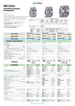
CBC Series with UL94V-0 polyamide insulating body • L94V-0 U • educed overall dimension r • patented “Easy bridge” system: double possibility to insert PTC multi pole cross-connections, without the need of insulating protection • mounting onto PR/3 type rails, according to IEC 60715 Std., “TH/35” type • available in grey RAL 7042 and beige RAL 1001 colours C certificate • ESI 08 ATEX 061 U Ex e I M2 / II 2 G D operating temperature range: –40 ÷ +80 °C • CoC IEC Ex N. CES 09.0002U x e II E The /GR tag indicates the grey colour version. Single or parallel extending PTC jumper configurations Adjacent...
Open the catalog to page 4All Cabur catalogs and technical brochures
 MarKing Pro
1 Page
 Photovoltaic Catalog
108 Pages
 terminal blocks catalog
200 Pages
 products for installation
28 Pages
 industrial marking systems
64 Pages

Archived catalogs
 PHOTOVOLTAIC PLANTS
108 Pages
 Industrial marking systems
76 Pages
 Power supplies - short form
16 Pages
 Power supplies
61 Pages
 Electromechanical relay modules
29 Pages
 Terminals
11 Pages
 Photovoltaic connection systems
72 Pages
 Accessories for mounting rails
4 Pages


- DC power supply
- Electrical cable
- Data connector
- AC/DC power supply
- Rectangular housing
- Copper cable
- Copper electrical cable
- Surge protector
- Circular connector
- Power cable
- Single-output power supply
- Switching relay
- DIN rail lightning arrester
- Switching power supply
- Flexible cable
- Class II surge protector
- Flexible electrical cable