- Catalogs
- Cablecraft Motion Control
- Cablecraft Linkage
Cablecraft Linkage
1 /4Pages

Cablecraft Linkage
1 /4Pages
Catalog excerpts
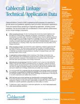
Cablecraft Linkage Technical/Application Data Cablecraft Motion Control’s (CMC) engineering staff possesses the expertise to provide advice and guidelines regarding nearly all motion transmission applications. There are several factors pertaining to engineering application, including correct installation, that should be taken into consideration to insure optimum performance of your chosen linkage components. When mounting ball studs, the hex mounting portion should be properly tightened and flat against its mating surface. Adequate countersinks, counterbores or washers may be necessary to provide a tight, flush joint. Installation torque values for tightening must be within the capacity of the linkage component or breakage may occur from over-tightening. Consult CMC’s engineering staff or refer to an appropriate engineering standard for mounting nut torque values associated with each grade of threaded fastener.Looseness in the threaded joint or mounting surface may cause abnormal wear and early failure of the linkage component. When mounting rod ends, care should be used in tightening a fastener against the ball to prevent distortion.The same torque requirements that apply to threaded fasteners also apply to securing the rod end spherical ball. The plated ball may become chipped or distorted by excessive clamping pressure, resulting in increased torque, wear, and premature failure of the rod end. In applications involving vibration where loosening of the linkage components may occur, self-locking nuts or lockwashers should be used to secure the components and prevent loosening. Looseness in the threaded joint or mounting surface may cause abnormal wear and early failure of the linkage component. Ball joints and rod end bearings should be mounted in such a way as to best utilize the design of the joint with respect to gravitational force. For example, a ball joint should be mounted with the housing member on top of the ball stud. Mounting the housing component with it’s weight and linkage hanging from the ball or ball stud could accelerate wear and lead to detachment of linkage components and sudden loss of control. It is recommended that a separate stop be incorporated in the linkage system to eliminate the possibility of exceeding the misalignment capability of the ball joint or rod end bearing. An overtravel condition of this type may result in breakage and detachment of the ball joint or rod end components and sudden loss of control. CMC ball joints and rod end bearings are manufactured to commercial standards. If you have questions concerning a particular product for your application, CMC can offer assistance; however, it is the end user’s responsibility to determine if the chosen part is suitable for a specific application (especially true where safety is a factor). To determine a part’s useful life for a particular application, you should test sample parts under actual operating conditions. Ultimate Radial Static Load Capacity (Rod Ends) These loads are the maximum amount of force the part can sustain before complete failure. All loads listed in the catalog are based on rod ends without grease fittings. Due to the removal of material for the fitting, the load rating for such a part is substantially lower. Consult CMC engineering for assistance on these parts. Radial Static Load Capacity (Spherical Bearings) These loads are the maximum amount of force the part can sustain before a 2% permanent set occurs in the part.Consult CMC engineering if these numbers don’t fit your application. Static Limit Load (Spherical Bearings) Static limit load is the allowable load that can be applied to a bearing without adversely affecting its performance capabilities. iBejnuoft Cablecraft Motion Controls
Open the catalog to page 1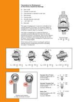
Calculations for Misalignment of Rod Ends & Spherical Bearings B = Bore of ball C = Chamfer on outer race D = Head diameter or diameter of outer race E = Ball diameter H = Housing width S = Shoulder diameter (neck ball) V= W = Ball width The angle of misalignment in a rod end is controlled by the outside diameter of the head. The maximum degree of misalignment is obtained when the head contacts the side of the fork or clevis in which it is mounted. The angle of misalignment in a spherical bearing is calculated somewhat differently from that of the rod end because the housing is not spherical....
Open the catalog to page 2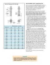
Dimensions in Inches THREAD OD N P N P Rod Ends/Ball Joints: Specifying Tips Each of our products are specifically designed to perform in even the most extreme conditions. Through this technical guide and the advice of our sales and engineering staff, our goal is to help you identify the most appropriate Cablecraft product suited to your application. First, a few key considerations... While the applications are almost limitless, the conditions that the different linkages witness are often very similar. When designing a linkage solution, keep in mind everything from environmental conditions (humidity,...
Open the catalog to page 3
2110 Summit Street New Haven, Indiana USA 46774 Tel 260 749-5105 Fax 260 749-5677 4401 South Orchard Street Tacoma, Washington 98411 USA Tel 253 475-1080 Fax 253 474-1623 120-6255 Diplocks Way-South Road Hailsham, East Sussex BN27 3JF, England Tel 44 1323 841510 Fax 44 1323 845848 © 2010 Cablecraft Motion Controls
Open the catalog to page 4All Cablecraft Motion Control catalogs and technical brochures
 Throttle Pedal – Heavy Duty
2 Pages
 Pull-Only Tension Controls
2 Pages
 Connecting a World in Motion
84 Pages
 Push-Pull Standard
4 Pages
 Micro Adjust Control Heads
2 Pages
 Non-Lock Control Heads
2 Pages
 Twist Lock Industrial
2 Pages
 High-Temp Rod Ends/Linkages
4 Pages
 Unidrum Lever
4 Pages
 Push-Pull 4B
4 Pages
 SR-G Ball Joints
2 Pages
 COM-P Sperical Bearings
2 Pages
 Leverstak
2 Pages
 Micro Adjust Industrial
2 Pages
 Button Lock Performance
2 Pages
 Pull-Only T-Flex
2 Pages
 Pull-Only Tension Cables
2 Pages
 R-G Ball Joints
2 Pages
 J/JM Sperical Bearings
2 Pages
 DBM and DBF Rod Ends
2 Pages


Archived catalogs
 DC/DH Control Swivels
2 Pages
 Manual Transmission Shifter
4 Pages
 Hardware_End
4 Pages
 Hardware/ End Fittings
4 Pages
 Turbo & EGR Platforms & Beyond
12 Pages
 Button Lock
2 Pages
 Pull-Only Clutch
4 Pages
 Push-Pull Cable - 4B
4 Pages
 Pull-Only Cable - T-Flex
2 Pages
 Pull-Only Cable - Tension
2 Pages
 Pull-Only Clutch Cable
4 Pages
 Custom Linkage Assemblies
2 Pages
 Performance Push-Pull Cable
2 Pages
 DBM/DBF
2 Pages
 Custom Cable Assemblies
2 Pages
 Hardware/End Fittings
4 Pages
 Custom Hand Controls
4 Pages
 Leverstack Hand Control
2 Pages
 Unidrum Lever - METRIC
4 Pages
 Undidrum Lever
4 Pages
 Light Duty Lever
2 Pages
 Brake Lever
4 Pages
 Pull-Only Brake Cable
4 Pages
 Push-Pull Cable - Standard
4 Pages
 Linkage Assemblies - Custom
2 Pages


