- Catalogs
- burster präzisionsmesstechnik gmbh & co kg
- USER MANUAL-Typ 9186-VX1XX DIGITAL INDICATOR FOR LOAD CELL INPUT
- Company
- Products
- Catalogs
- News & Trends
- Exhibitions
USER MANUAL-Typ 9186-VX1XX DIGITAL INDICATOR FOR LOAD CELL INPUT
1 /24Pages

USER MANUAL-Typ 9186-VX1XX DIGITAL INDICATOR FOR LOAD CELL INPUT
1 /24Pages
Catalog excerpts

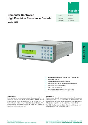
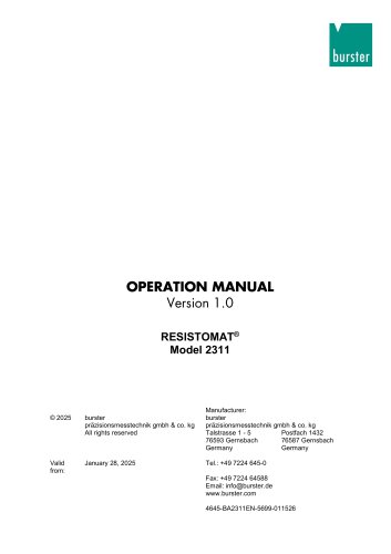
USER MANUAL Typ 9186-VX1XX DIGITAL INDICATOR FOR LOAD CELL INPUT
Open the catalog to page 1
Typ 9186-VX1XX GENERAL INFORMATION This manual does not constitute a contract or a commitment on the part of burster präzisionsmesstechnik gmbh & co kg. All information contained in this document is subject to change without prior notice. MANUAL VALID FOR INSTRUMENTS WITH C2.00 SOFT VERSION OR HIGHER Package contents With the instrument it is also supplied: Quick installation guide. Mounting panel accessories (a sealing gasket and 2 fixing clips). Wiring accessories (plug-in terminal block connectors and 2 key tools for cable insertion). 4 adhesive labels set with engineering units. General...
Open the catalog to page 3
To guarantee instrument accuracy, it is recommended to checking its compliance according to the technical specifications listed in this manual, performing calibrations regularly in accordance to operation criteria in each application. Instrument calibration and/or adjustment should be performed only by an accredited laboratory or directly by the manufacturer. Instrument repairs should only be carried out by the manufacturer or by its authorized partners. For frontal device cleaning, just wipe it with a damp cloth and neutral soap product. DO NOT USE SOLVENTS!.
Open the catalog to page 4
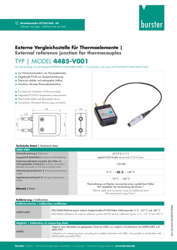
EU-Konformitatserklarung (nach en iso/iec 17050-1:2010) EU-Declaration of conformity (in accordance with EN ISO/IEC 17050-1:2010) Name des Ausstellers: burster prazisionsmesstechnik gmbh & co kg Issuer’s name: Anschrift des Ausstellers: Issuer’s address: Gegenstand der Erklarung: Object of the declaration: Talstr. 1-5 76593 Gernsbach, Germany Digitalanzeiger / DIGILOW Digital Display/DIGILOW Model number /type: Diese Erklarung beinhaltet obengenannte Produkte mit alien Optionen This declaration covers all options of the above product(s) Das oben beschriebene Produkt ist konform mit den Anforderungen...
Open the catalog to page 5
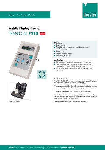
Typ 9186-VX1XX Device description All information contained in this manual is valid for Typ 9186-VX1XX models. Typ 9186-VX1XX models are digital indicators fully configurables that allow input type selection in order to be used as needed. Available signal inputs are the following: LOAD CELL (30mV, 300mV) The basic instrument consists of a soldered assembly composed of a main board, a display and an input signal circuits. It can also be incorporated, as an option, an extra plug-in 2 SPDT 8A relays circuit output which is isolated from signal input and power supply. This extra circuit has independent...
Open the catalog to page 6
There are two main function modes: RUN and PRO. PRO mode is when configuration menu is entered to programm the indicator, whereas RUN is the normal mode in which display shows the reading according to configuration and input signal value. The table below summarizes display parts description and LEDs and keyboard function. Installing and connecting recommendations This instrument coforms with the following community directives: EMC 2004/108/CE and LVD 2006/95/CE. Refer to the instructions in this manual to preserve safety protections. WARNING: If this instrument is not installed and used in accordance...
Open the catalog to page 7
Basic instrument has two rear connectors CN1 and CN2. If 2RE output option card is installed, two more connectors CN3 and CN4 appear. See all four connectors location and their pin out in the right figure. All female provided terminal connectors are of CAGE CLAMP® technology. Terminals for CN2 connector admit cables with section from 0.2mm2 up to 1.5mm2 (AWG 24^14). Terminals for CN1, CN3 and CN4 connectors admit cables with section from 0.08mm2 up to 2.5mm2 (AWG 28^12). To perform wiring connections, strip the cable leaving from 7 to 10mm exposed to air, insert it in the proper terminal while...
Open the catalog to page 8
Typ 9186-VX1XX CONNECTION TO A GROUP OF LOAD CELLS WITH EXTERNAL EXCITATION GROUP OF LOAD CELLS ±30mV ±300mV WIRING DETAIL CONNECTION FOR n LOAD CELLS WITH EXTERNAL EXCITATION Remote TARE function wiring diagram O.C. OUTPUT INDICATOR CONTACT SWITCH INDICATOR NOTE: When using an open collector output, the external electronic circuit connected between pin 4 and pin 5 of CN2 input connector, must be able to provide a current of 4mA and withstand up to 40V. In both cases remote TARE is activated when contact is closed less than 3 seconds. Remote TARE RESET is identically activated through these pins...
Open the catalog to page 9
Typ 9186-VX1XX INPUT CONFIGURATION Configuration menu When connecting instrument to Power supply, display test begins automatically to check the good function of LEDs and digits, once this test is finished, display shows internal software version and then the unit goes to RUN mode. Configuration software has a hierarchical structure composed of a number of menus and submenus. By pressing ENTER key, display shows “Pro”, a new pressing brings access to main menu where appear configuration menus, that is, input configuration (InP), display configuration (dSP) and setpoints configuration (SEtP)....
Open the catalog to page 10
EXCITATION LEVEL: Configurable value: E 5: 5V DC E 10: 10V DC Once input range is selected, the routine goes to configure excitation. 5V and 10V are available. In both cases load current limit is 30mA DC.
Open the catalog to page 11
Typ 9186-VX1XX DISPLAY CONFIGURATION Display Programming The second menu corresponds to display configuration. This, in turn, consists of some submenús: through frontal keys configuration (SCAL), through real input signal (TEACH) (tEAC) and reading stabilization filter (FiLt). TRHOUGH FRONTAL KEYS CONFIGURATION “SCAL” Input and display values are configured manually through the three keys of the instrument. This method is suitable when signal values supplied by the transducer at each extreme point of the process are known. REAL INPUT SIGNAL CONFIGURATION “tEAC” Input values are directly introduced...
Open the catalog to page 12
For both display scaling "SCAL" and "tEAC" methods, parameters to be sequentially introduced are identical. It only must be considered that in "SCAL" method, all values must be manually introduced through the three frontal keys whereas in " tEAC" method, input signal value must be present at the conector at each point that is intended to be configured. FIRST POINT INPUT AND DISPLAY VALUE: InP1: Input value indication. 0000: Value entering in counts within available model display range. dSP1: Display value indication. 0000: Value entering in counts within available model display range. DECIMAL...
Open the catalog to page 13All Burster präzisionsmesstechnik gmbh & co kg catalogs and technical brochures
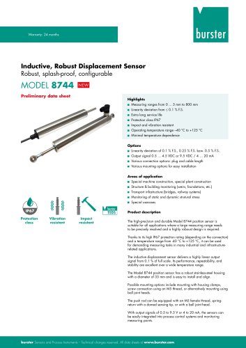 Data Sheet Model 8744
6 Pages
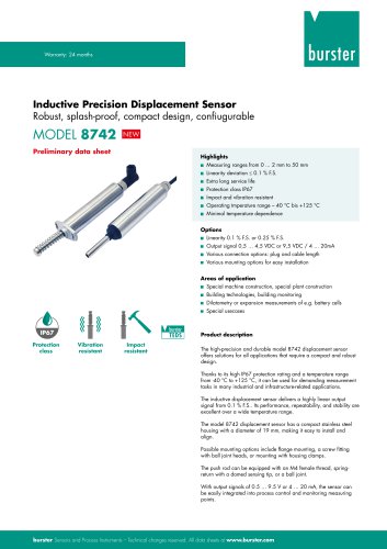 Data Sheet Model 8742
6 Pages
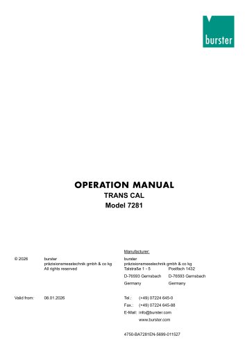
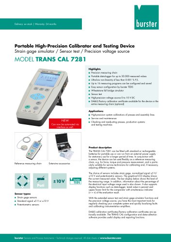 Data Sheet Model 7281
5 Pages
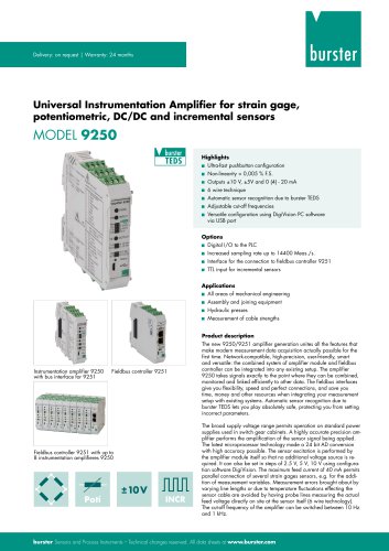 Data Sheet Model 9250
7 Pages
 Operation manual 2025
76 Pages
 Data Sheet Model 8523 (2025)
8 Pages
 Data-Sheet- Model 8228
6 Pages
 Data Sheet Model 8656
7 Pages
 Load cells
25 Pages
 Data Sheet Model 8510 (2025)
5 Pages
 Data-Sheet - 9251
6 Pages
 Data sheet Model 8631
5 Pages
 Data Sheet Model 2511
6 Pages
 Data Sheet Model 2311
5 Pages
 Data Sheet Model 4463
5 Pages
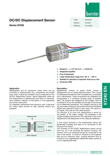 Data Sheet Typ 87240
2 Pages
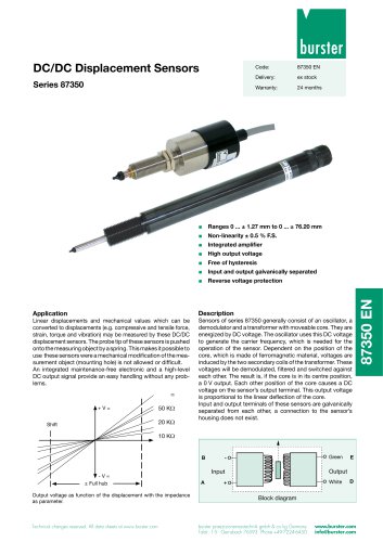 Data Sheet Series 87350
2 Pages
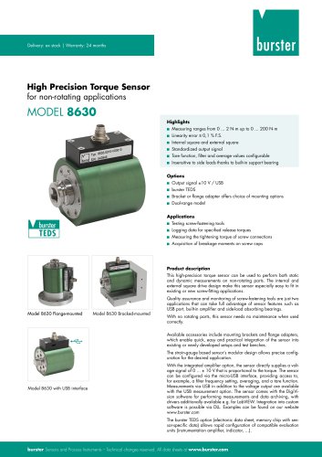 Data Sheet Model 8630
6 Pages
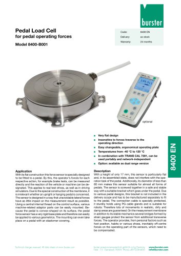 Data Sheet Model 8400-B001
2 Pages
 Load-cell
25 Pages
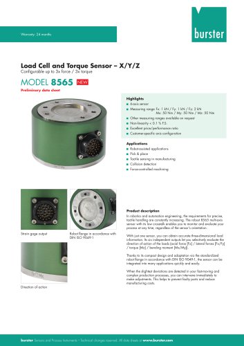 Data Sheet Motel 8565 (2025)
5 Pages
 Torque Sensors
9 Pages
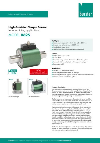 Data Sheet Typ 8625
7 Pages
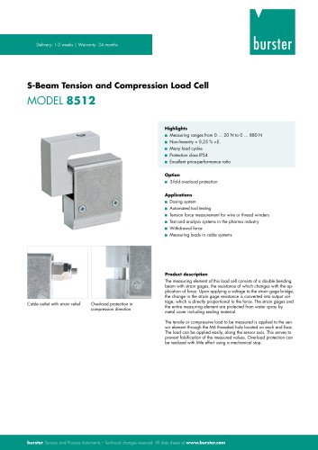 Data Sheet Typ 8512 (2025)
5 Pages
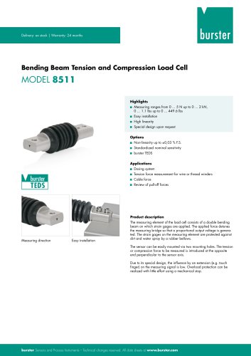 Data Sheet Model 8511 (2025)
6 Pages
 Data Sheet Model 8415 (2025)
6 Pages
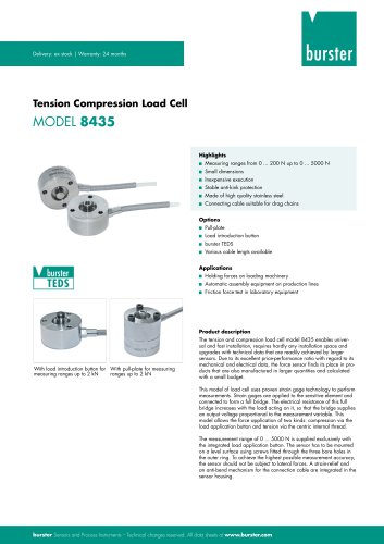 Data sheet Model 8435 (2025)
7 Pages
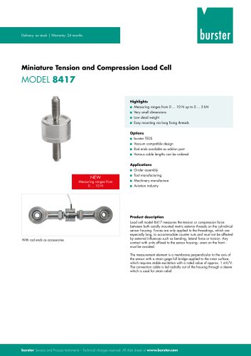 Data Sheet Typ 8417 (2025)
7 Pages
 Data Sheet Typ 8532 (2025)
2 Pages
 Data Sheet 8427 (2025)
7 Pages
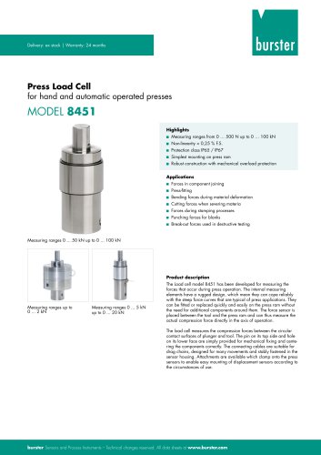 Data Sheet Motel 8451 (2025)
7 Pages
 Data Sheet Model 8527 (2025)
7 Pages
 Data Sheet Model 8526 (2025)
9 Pages
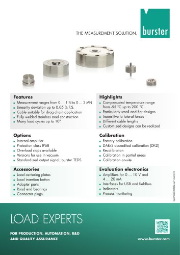 Flyer Load Experts 2025
1 Page
 Data sheet Typ 8416 (2025)
6 Pages
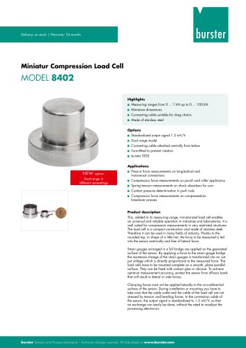 Data Sheet Model 8402 (2025)
6 Pages
 2511 BATTERY MEASURING MODULE
14 Pages
 Data Sheet- Model 2500-Z100
2 Pages
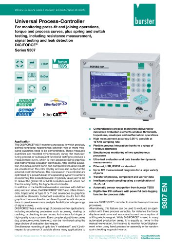 Data Sheet Typ 9307
6 Pages
 Data Sheet Model 9210
5 Pages
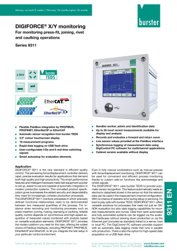 Data Sheet Typ 9311
6 Pages
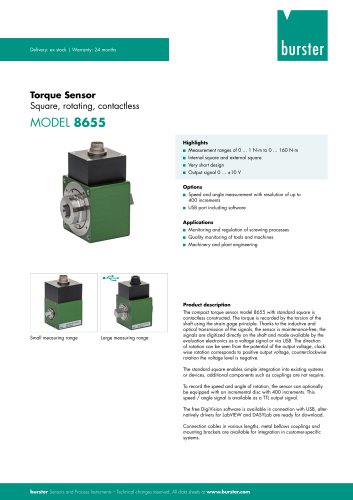 Data Sheet Typ 8655 (2025)
7 Pages
 Displacement Sensors 2025
2 Pages
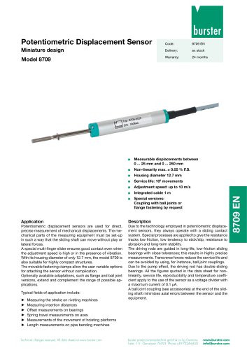 Data sheet Model 8709 (2025)
2 Pages
 Data sheet Model 8709
2 Pages
 Data Sheet Typ 8655
7 Pages
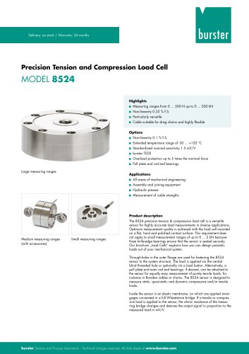 Data Sheet Model 8524
8 Pages
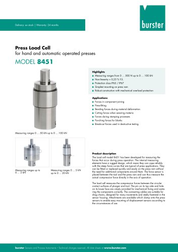 Data Sheet Motel 8451
7 Pages
 Data Sheet Typ 8627
2 Pages
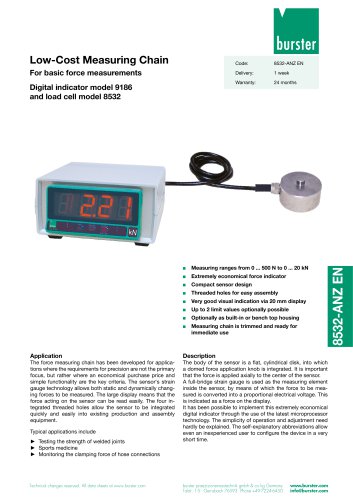
 Data Sheet Model 9186/8532
2 Pages
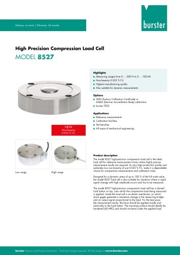 Data Sheet Model 8527
7 Pages
 Data Sheet Typ 8512
5 Pages
 Data Sheet Model 8511
6 Pages
 Data Sheet Typ 8625
7 Pages
 Data Sheet Motel 8565
5 Pages
 Data Sheet Typ 8532
2 Pages
 Data Sheet Model 8561
6 Pages
 Data Sheet Model 8510
5 Pages
 Data Sheet Model 8523
8 Pages
 Data Sheet Model 8526
9 Pages
 Data Sheet Typ 8417
7 Pages
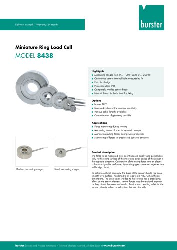 Data Sheet - Model 8438
6 Pages
 Data sheet Model 8435
7 Pages
 Data Sheet 8427
7 Pages
 Data Sheet Model 8402
6 Pages
 Data sheet Typ 8416
6 Pages
 Press fitting - the reliable way
11 Pages
 Data Sheet Model 9243
2 Pages
 Displacement Sensors
2 Pages
 Flyer Load Experts
1 Page
 Sensor Solutions
1 Page
 Data Sheet Model 9235
2 Pages
 Data sheet Series 8738
2 Pages
 Flyer Battery Tester
1 Page
 Data Sheet Model 2560
5 Pages
 Operation manual
76 Pages
 Data Sheet Typ 8739
2 Pages
 RESISTOMAT® Model 2329
4 Pages
 Data Sheet Model 2550
4 Pages
 Data Sheet Typ 8645
5 Pages
 Flyer Displacement Sensor
2 Pages
 Data Sheet - Model 8670
4 Pages


Archived catalogs
 Data Sheet Model 8415
6 Pages

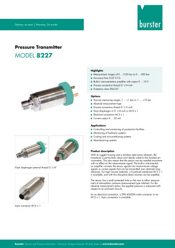
- Pressure transmitter
- BURSTER tension/compression load cell
- BURSTER steel load cell
- Calibration system
- Analog pressure transmitter
- BURSTER strain gauge load cell
- BURSTER stainless steel load cell
- Waterproof pressure transmitter
- Membrane pressure transmitter
- Stainless steel pressure transmitter
- Panel panel meter
- Relative pressure transmitter
- Position transducer
- Signal amplifying integrated circuit
- Beam type force sensor
- BURSTER compression load cell
- Automated software