
- Catalogs
- burster präzisionsmesstechnik gmbh & co kg
- Operation Manual Model 8565

Operation Manual Model 8565
1 /24Pages
Operation Manual Model 8565
1 /24Pages
Catalog excerpts
prazisionsmesstechnik gmbh & co kg prazisionsmesstechnik gmbh & co kg All rights reserved Talstrasse 1 - 5 Postfach 1432 Germany Germany Fax: +49 7224 645-88 Email: [email protected] www.burster.de
Open the catalog to page 1
Warranty disclaimer All information in the present documentation was prepared and compiled with great care and reproduced in accordance with effective control measures. No warranty is provided for freedom from errors. We reserve the right to make technical changes. The present information as well as the corresponding technical data can change without notice. Reproduction of any part of this documentation or its processing or revision using electronic systems is prohibited without the manufacturer’s prior written approval. Components, devices and measurement sensors made by burster präzisionsmesstechnik...
Open the catalog to page 2
This operation manual is intended to help familiarize you with the device and obtain the full functional benefit from its capabilities. The operation manual contains important information for the safe, proper and effective use of the device. Follow the instructions carefully to reduce repair costs and downtime, and to increase the reliability and service life of the device. This operation manual applies exclusively to the model 8565 load cell and torque sensor (henceforth: “sensor”). This operation manual is intended for personnel who install and operate the sensor. To enable you to work quickly...
Open the catalog to page 5
Conversions and modifications Note: The warranty shall be deemed void immediately if you open or dismantle the sensor during the warranty period. The sensor does not contain any parts that are intended to be serviced by the user. Only the manufacturer’s own qualified personnel are permitted to open the sensor. It is not permitted to make any changes to the sensor without the written agreement of burster präzisionsmesstechnik gmbh & co kg. burster präzisionsmesstechnik gmbh & co kg does not accept liability for damages or injury if this condition is disregarded.
Open the catalog to page 6
IMPORTANT: Read the operation manual carefully before using the device, and keep it for future reference. 2.1 Applications2.1.1 Intended use The sensor is intended mainly for force/torque measurements in production facilities, units newtons (N) and newtonmeters (Nm). The local acceleration due to gravity (g = 9.81 m/s2) must be taken into account when determining masses. 2.1.2 Restrictions on use The sensor does not pose a hazard if used within its specification and in accordance with safety regulations. The manufacturer does not accept liability for any personal injury or property damage arising...
Open the catalog to page 7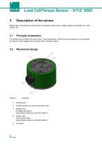
Load Cell/Torque Sensor - X/Y/Z 85653 Description of the sensor Please refer to the sensor’s data sheet for full details of dimensions, weight, degree of protection etc. (see section 15). The sensor has an internal structure which, under deformation, allows forces and torques to be measured by means of strain gages and converted into an electrical signal. 2 Contact surfaces for force transmission (4x) (robot flange conforms to DIN ISO 9409-1) (robot flange conforms to DIN ISO 9409-1)
Open the catalog to page 8
Requirements for accurate measured values Full-scale deflection The applied forces and torques deform the sensor by approx. 15 µm to 40 µm, depending on the load direction. This deformation is known as the “full-scale deflection”, and is so small that it cannot be seen with the naked eye. Crosstalk means the mutual influence of the individual channels on each other. If one component is loaded, the other channels show a very small, unwanted signal. It is only possible to specify the crosstalk if the sensor measures several components (forces Fx, Fy, Fz or torques Mx, My, Mz). The quality of the...
Open the catalog to page 9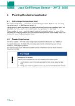
Planning the desired application Calculating the maximum load The maximum limit value (Lmax) must not be exceeded with dynamic loads. The formula for calculating Lmax can be found in the data sheet (see section 15). Use the formula to add up the maximum occurring force and torque vectors with a weighting factor. The calculated value for Lmax must remain smaller than the value specified in the data sheet. Please note that the sensor’s coordinate origin is located at the geometric center of the sensor. When calculating the maximum operational force, the additional bending moments due to leverage...
Open the catalog to page 10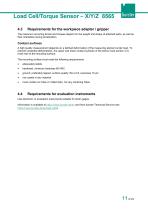
The maximum occurring forces and torques depend on the weight and shape of attached parts, as well as their orientation during acceleration. Contact surfaces A high quality measurement depends on a defined deformation of the measuring element under load. To prevent unwanted deformations, the upper and lower contact surfaces of the sensor (see section 3.2) must rest on the mounting surface. The mounting surface must meet the following requirements: • adequately stable • hardened, minimum hardness 60 HRC • ground, preferably lapped, surface quality: Ra < 0.8, evenness 10 pm • must contain no holes...
Open the catalog to page 11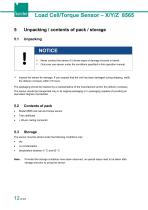
Load Cell/Torque Sensor - X/Y/Z 85655 Unpacking / contents of pack / storage5.1 Unpacking ► Never connect the sensor if it shows signs of damage incurred in transit. ► Only ever use sensor under the conditions specified in this operation manual. ► Inspect the sensor for damage. If you suspect that the unit has been damaged during shipping, notify the delivery company within 72 hours. The packaging should be retained by a representative of the manufacturer and/or the delivery company. The sensor should be transported only in its original packaging or in packaging capable of providing an equivalent...
Open the catalog to page 12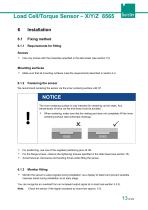
Load Cell/Torque Sensor - X/Y/Z 85656 Installation6.1 Fixing method6.1.1 Requirements for fitting Screws ► Use only screws with the properties specified in the data sheet (see section 15). Mounting surfaces ► Make sure that all mounting surfaces meet the requirements described in section 4.3. 6.1.2 Fastening the sensor We recommend centering the sensor via the inner centering surface 046 H7. The inner centering surface is only intended for centering via the sides. Any transmission of force via the end faces must be avoided. ► When centering, make sure that the mating part does not completely...
Open the catalog to page 13All Burster präzisionsmesstechnik gmbh & co kg catalogs and technical brochures
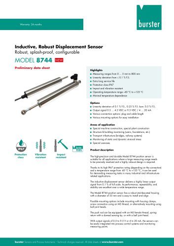 Data Sheet Model 8744
6 Pages
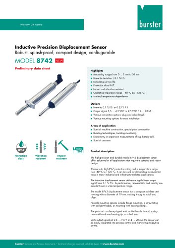 Data Sheet Model 8742
6 Pages
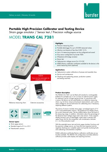 Data Sheet Model 7281
5 Pages
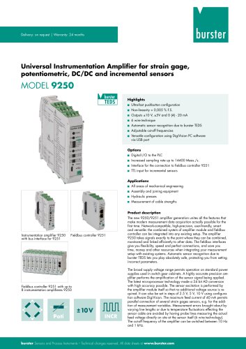 Data Sheet Model 9250
7 Pages
 Operation manual 2025
76 Pages
 Data Sheet Model 8523 (2025)
8 Pages
 Data-Sheet- Model 8228
6 Pages
 Data Sheet Model 8656
7 Pages
 Brochure Load Cell
25 Pages
 Data Sheet Model 8510 (2025)
5 Pages
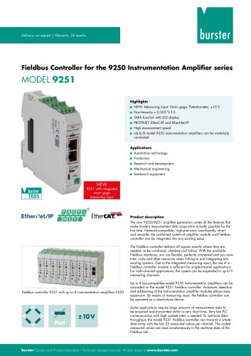 Data-Sheet - 9251
6 Pages
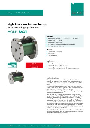 Data sheet Model 8631
5 Pages
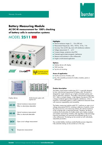 Data Sheet Model 2511
6 Pages
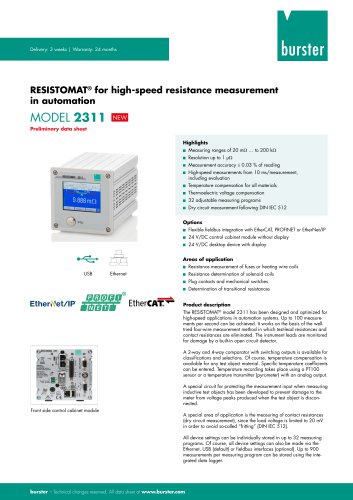 Data Sheet Model 2311
5 Pages
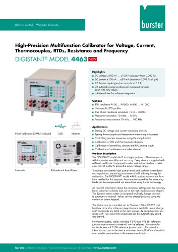 Data Sheet Model 4463
5 Pages
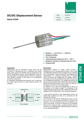 Data Sheet Typ 87240
2 Pages
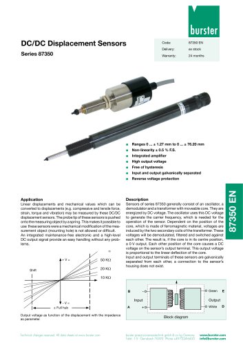 Data Sheet Series 87350
2 Pages
 Data Sheet Model 8630
6 Pages
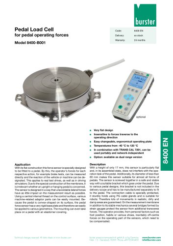 Data Sheet Model 8400-B001
2 Pages
 Load-cell
25 Pages
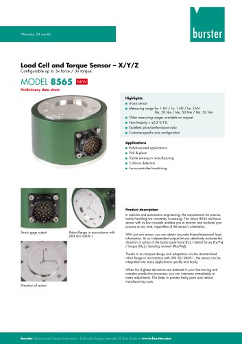 Data Sheet Model 8565
5 Pages
 Torque Sensors
9 Pages
 Data Sheet Typ 8625
7 Pages
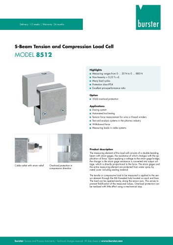 Data Sheet Typ 8512 (2025)
5 Pages
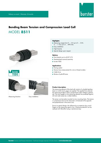 Data Sheet Model 8511 (2025)
6 Pages
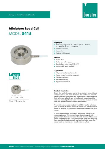 Data Sheet Model 8415 (2025)
6 Pages
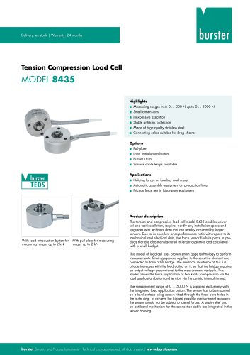 Data sheet Model 8435 (2025)
7 Pages
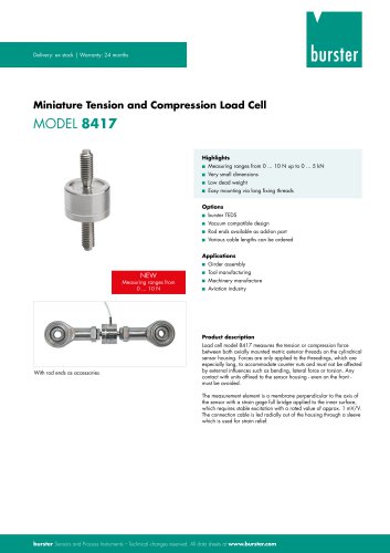 Data Sheet Typ 8417 (2025)
7 Pages
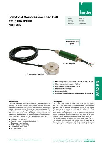 Data Sheet Typ 8532 (2025)
2 Pages
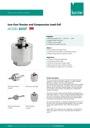 Data Sheet 8427 (2025)
7 Pages
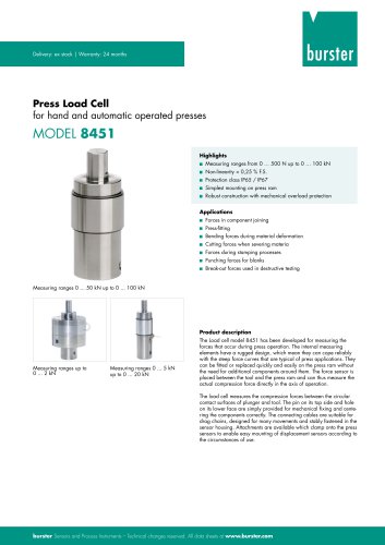 Data Sheet Motel 8451 (2025)
7 Pages
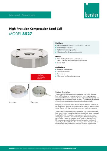 Data Sheet Model 8527 (2025)
7 Pages
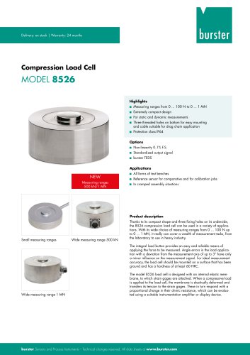 Data Sheet Model 8526 (2025)
9 Pages
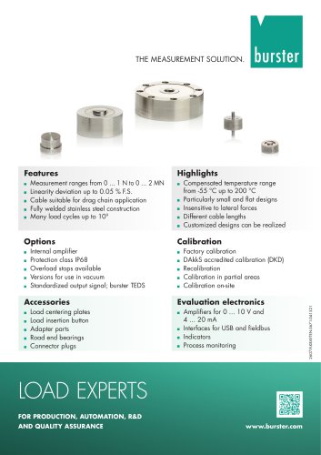 Flyer Load Experts 2025
1 Page
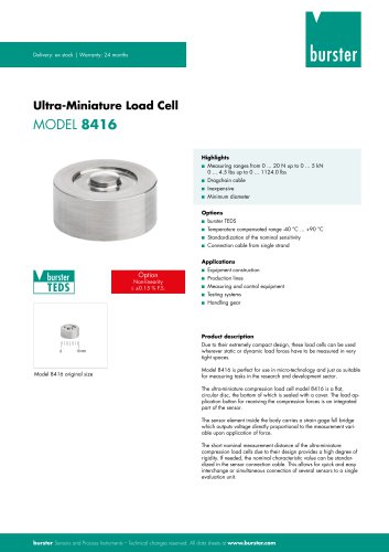 Data sheet Typ 8416 (2025)
6 Pages
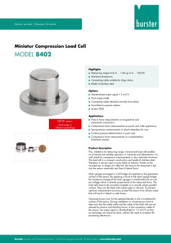 Data Sheet Model 8402 (2025)
6 Pages
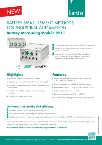
 2511 BATTERY MEASURING MODULE
14 Pages
 Data Sheet- Model 2500-Z100
2 Pages
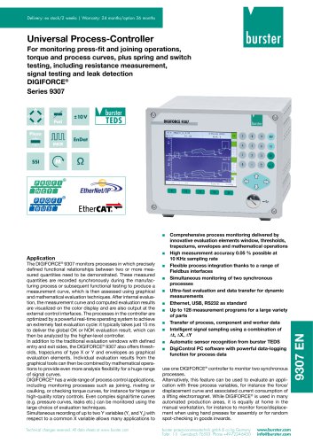 Data Sheet Typ 9307
6 Pages
 Data Sheet Model 9210
5 Pages
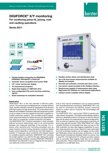 Data Sheet Typ 9311
6 Pages
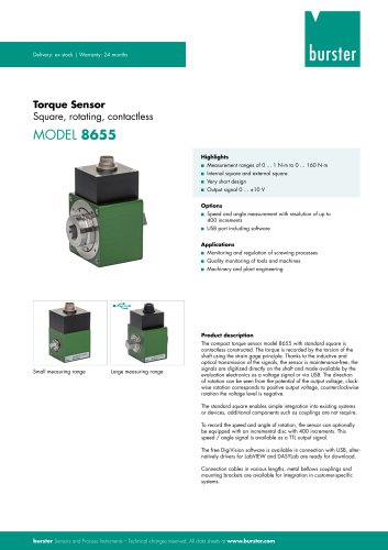 Data Sheet Typ 8655 (2025)
7 Pages
 Displacement Sensors 2025
2 Pages
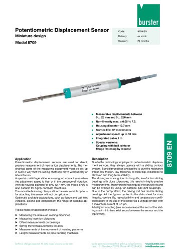 Data sheet Model 8709 (2025)
2 Pages
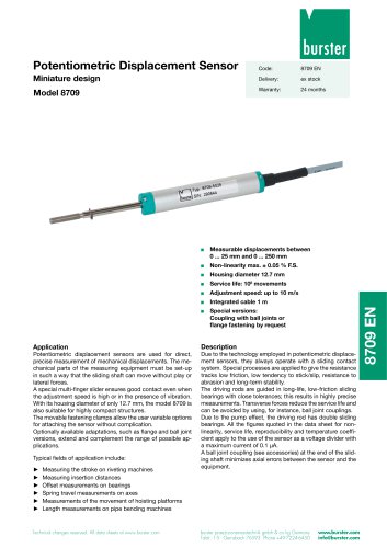 Data sheet Model 8709
2 Pages
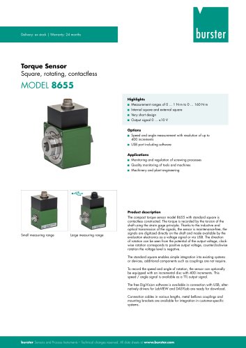 Data Sheet Typ 8655
7 Pages
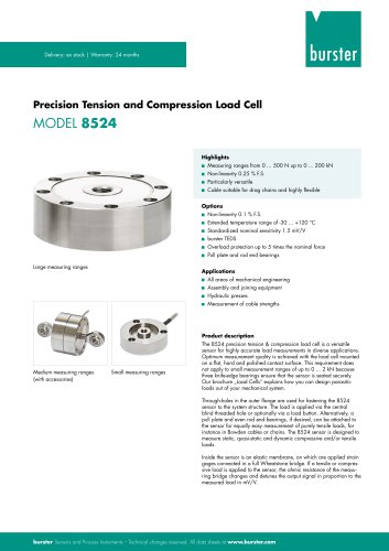 Data Sheet Model 8524
8 Pages
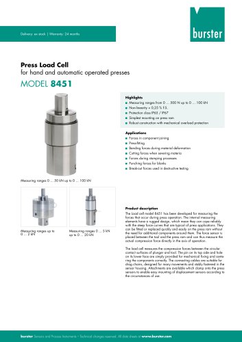 Data Sheet Motel 8451
7 Pages
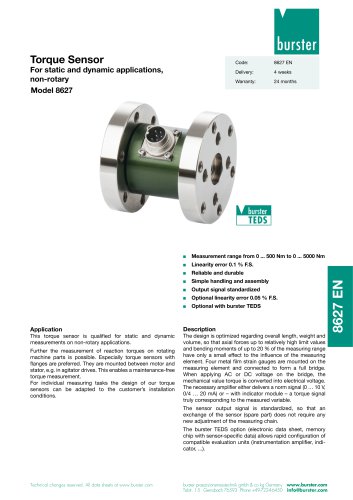 Data Sheet Typ 8627
2 Pages
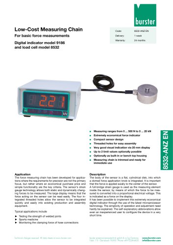 Data Sheet Model 9186/8532
2 Pages
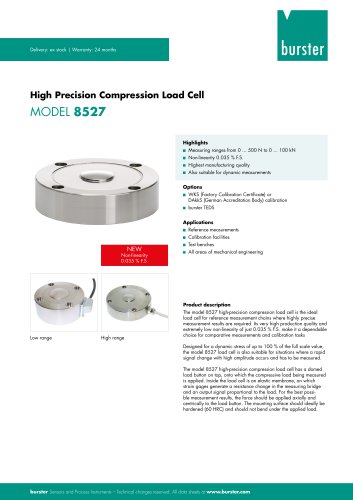 Data Sheet Model 8527
7 Pages
 Data Sheet Typ 8512
5 Pages
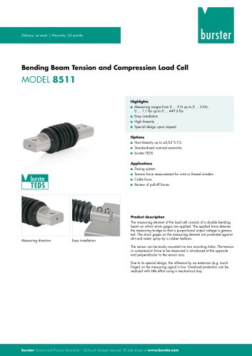 Data Sheet Model 8511
6 Pages
 Data Sheet Typ 8625
7 Pages
 Data Sheet Typ 8532
2 Pages
 Data Sheet Model 8561
6 Pages
 Data Sheet Model 8510
5 Pages
 Data Sheet Model 8523
8 Pages
 Data Sheet Model 8526
9 Pages
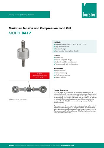 Data Sheet Typ 8417
7 Pages
 Data Sheet - Model 8438
6 Pages
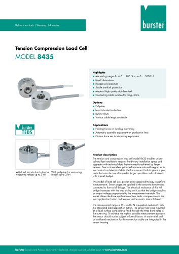 Data sheet Model 8435
7 Pages
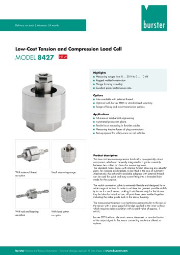 Data Sheet 8427
7 Pages
 Data Sheet Model 8402
6 Pages
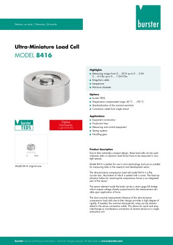 Data sheet Typ 8416
6 Pages
 Press fitting - the reliable way
11 Pages
 Data Sheet Model 9243
2 Pages
 Displacement Sensors
2 Pages
 Flyer Load Experts
1 Page
 Sensor Solutions
1 Page
 Data Sheet Model 9235
2 Pages
 Data sheet Series 8738
2 Pages
 Flyer Battery Tester
1 Page
 Data Sheet Model 2560
5 Pages
 Operation manual
76 Pages
 Data Sheet Typ 8739
2 Pages
 RESISTOMAT® Model 2329
4 Pages
 Data Sheet Model 2550
4 Pages
 Data Sheet Typ 8645
5 Pages
 Flyer Displacement Sensor
2 Pages
 Data Sheet - Model 8670
4 Pages
























Archived catalogs
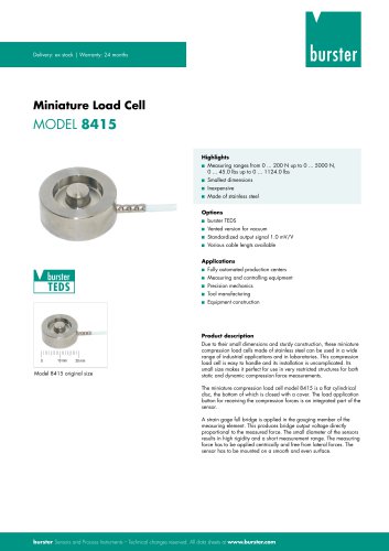 Data Sheet Model 8415
6 Pages

- Display module
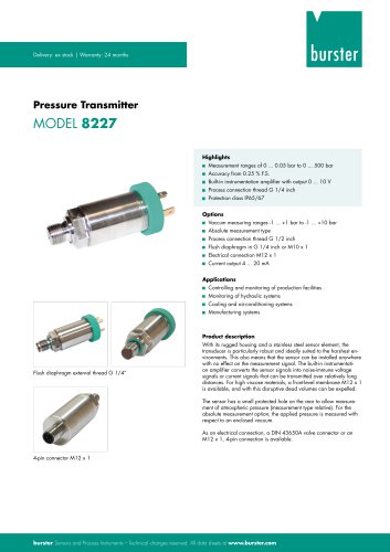
- Pressure transmitter
- BURSTER tension/compression load cell
- BURSTER steel load cell
- Calibration system
- Analog pressure transmitter
- BURSTER strain gauge load cell
- Digital indicator
- BURSTER stainless steel load cell
- Waterproof pressure transmitter
- Membrane pressure transmitter
- Stainless steel pressure transmitter
- Panel panel meter
- Relative pressure transmitter
- Position transducer
- Signal amplifying integrated circuit
- Beam type force sensor
- BURSTER compression load cell
- Automated software