- Catalogs
- burster präzisionsmesstechnik gmbh & co kg
- Data Sheet Precision Torque Sensor Model 8661
- Company
- Products
- Catalogs
- News & Trends
- Exhibitions
Data Sheet Precision Torque Sensor Model 8661
1 /9Pages
Data Sheet Precision Torque Sensor Model 8661
1 /9Pages
Catalog excerpts

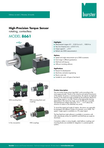
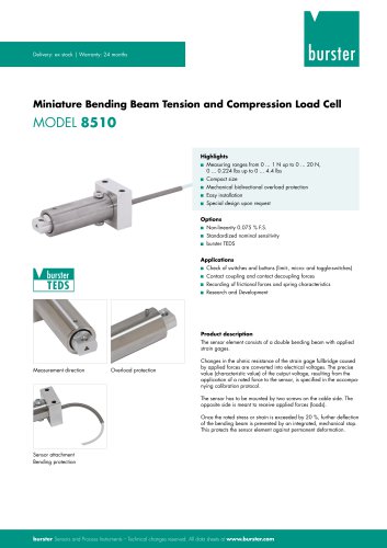
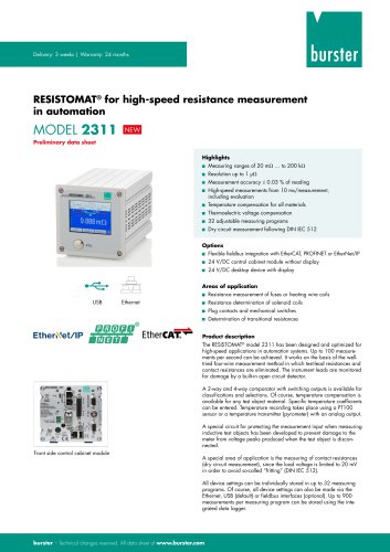
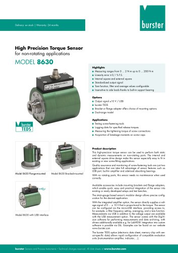
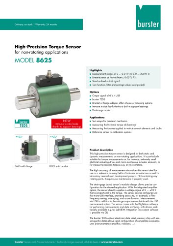
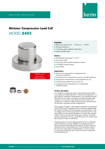
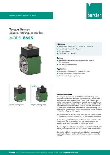
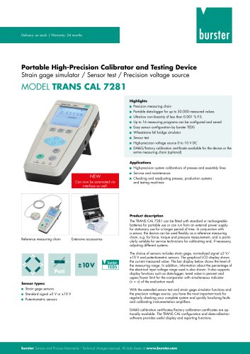
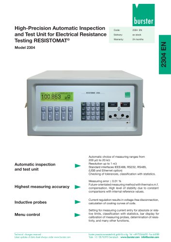
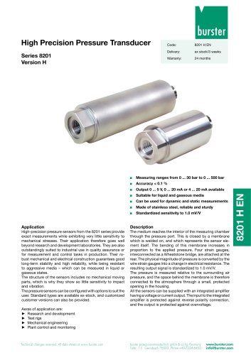
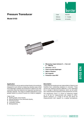
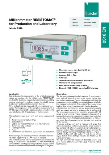
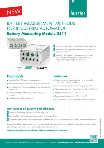
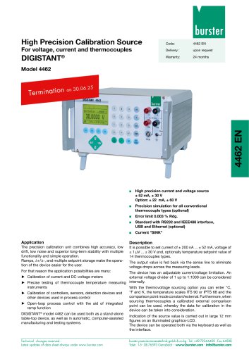
Delivery: ex stock | Warranty: 24 months rotating, contactless With mounting block and couplings Highlights ■ Measurement ranges of 0 ... 0.02 N-m to 0 ... 1000 N-m ■ Very low linearity error < ±0.05 % F.S. ■ Refresh rate 2000 measurements/s ■ Speed and angle measurement up to 2000 increments ■ Dual range in different graduations ■ Shaft end with keyway ■ USB port including software ■ Machinery and plant engineering ■ Electric motor test ■ Suitable for use in all types of test bench The non-contact torque sensor type 8661 works according to the strain gage principle. Thanks to the inductive and optical transmission of the signals, the sensor is maintenance-free, the signals are digitized directly on the shaft and made available by the evaluation electronics as a voltage signal or via USB. Thanks to the high-quality bearing, depending on the measuring range, up to 25,000 rpm is possible. The bidirectional voltage output from -10 V ... +10 V allows the direction of rotation to be identified very easily. To record the speed and angle of rotation, the sensor can optionally be equipped with different number of increments, up to 2000. This speed / angle signal is available as a TTL output signal. The free DigiVision Light software is available in connection with USB, alternatively drivers for LabVIEW and DASYLab are ready for download. Connection cables in various lengths, metal bellows couplings and mounting blocks are available for integration in customer-specific systems. burster Sensors and Process Instruments - Technical changes reserved. All data sheets at www.burster.com
Open the catalog to page 1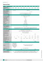
Relative non-linearity 0.1 % F.S. 0.05 % F.S. Relative non-linearity dual range sensor Relative hysteresis Tolerance of sensitivity Electrical values Rated supply voltage range Output voltage at ± rated torque Output resistance Insulation resistance Refresh rate Ripple Control signal Environmental conditions Range of operating and nominal temperature Sensitivity of temperature effects Mechanical values Dynamic overload safe Max. operation torque Breakaway torque Alternating load Maximum limit axial load Maximum limit radial load Spring constant Mass moment of inertia measuring side Mass moment...
Open the catalog to page 2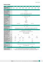
Do not exceed the permitted axial and radial forces during fitting and operation. Installation instructions Please refer to our operating instructions for detailed information www.burster.com. Suitable couplings should be used to avoid strain resulting from parallel or angular offset between the shafts. burster Sensors and Process Instruments - Technical changes reserved. All data sheets at www.burster.com
Open the catalog to page 3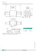
Dimensional drawing Measuring range* For detailed dimensions you can find sensor CAD data on our website www.burster.com. All dimensions without tolerance specifications comply with ISO 2768-fH. burster Sensors and Process Instruments - Technical changes reserved. All data sheets at www.burster.com
Open the catalog to page 4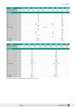
All dimensions without tolerance specifications comply with ISO 2768-fH. burster Sensors and Process Instruments - Technical changes reserved. All data sheets at www.burster.com
Open the catalog to page 5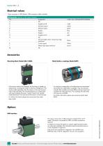
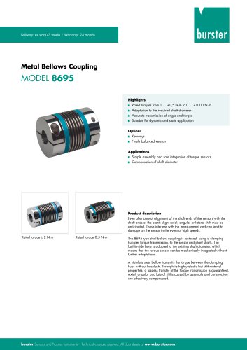
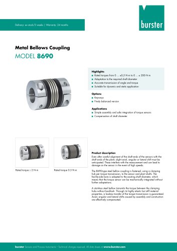
12-pin connector or USB (Option, USB connection cable included) For optimum compensation of misalignment we recommend torsionally free metal bellow couplings. They are characterized by their excellent torsional stiffness during torque load and their low restoring forces. The couplings are optionally with keyways available. For further information please see accessories data sheet 8695. If the sensor needs to be replaced, the locating pin speeds up replacement, avoiding the need for laborious realignment. This can be useful especially when the sensor is only used occasionally in the load path....
Open the catalog to page 6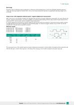
The sensor with two measuring ranges corresponds to its dimensions of the standard version, but has two separately calibrated measuring ranges. The measuring ranges are switched within <50 ms, even during measurement operation, by applying the operating voltage to pin L or via USB. For angular displacement measurement (or direction detection), both channels need to be evaluated. To achieve the maximum angular resolution, four-edge decoding must be used to read both the rising and falling edges. For instance an angular resolution of up to 0.045° can then be achieved with an encoder disk having...
Open the catalog to page 7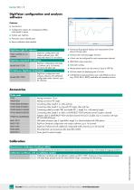
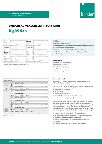
DigiVision configuration and analysis software Features ■ Configuration options for averaging and filters; value stored in sensor ■ Intuitive user interface ■ Automatic sensor identification ■ Sensor calibration data readout burster Sensors and Process Instruments - Technical changes reserved. All data sheets at www.burster.com
Open the catalog to page 8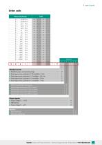
Order code Measuring Range Standard sensor Shaft ends with keyway 2 burster Sensors and Process Instruments - Technical changes reserved. All data sheets at www.burster.com
Open the catalog to page 9All Burster präzisionsmesstechnik gmbh & co kg catalogs and technical brochures
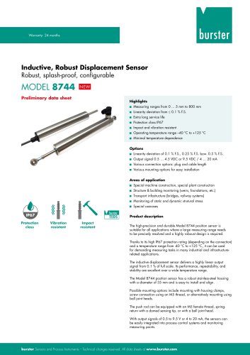 Data Sheet Model 8744
6 Pages
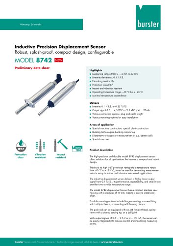 Data Sheet Model 8742
6 Pages
 Data Sheet Model 7281
5 Pages
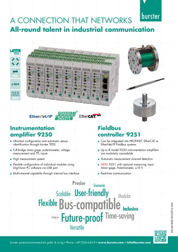
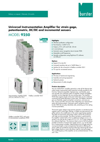 Data Sheet Model 9250
7 Pages
 Operation manual 2025
76 Pages
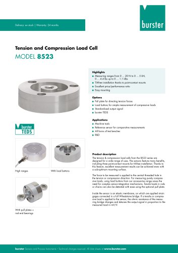 Data Sheet Model 8523 (2025)
8 Pages
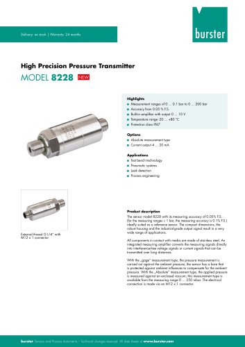 Data-Sheet- Model 8228
6 Pages
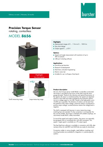 Data Sheet Model 8656
7 Pages
 Brochure Load Cell
25 Pages
 Data Sheet Model 8510 (2025)
5 Pages
 Data-Sheet - 9251
6 Pages
 Data sheet Model 8631
5 Pages
 Data Sheet Model 2511
6 Pages
 Data Sheet Model 2311
5 Pages
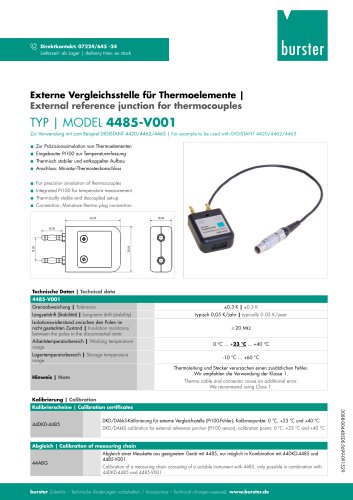
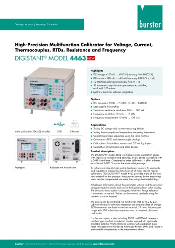 Data Sheet Model 4463
5 Pages
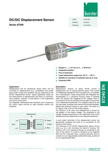 Data Sheet Typ 87240
2 Pages
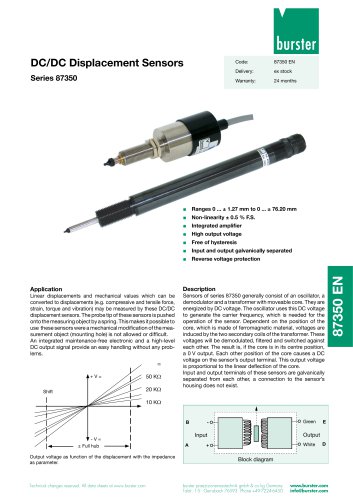 Data Sheet Series 87350
2 Pages
 Data Sheet Model 8630
6 Pages
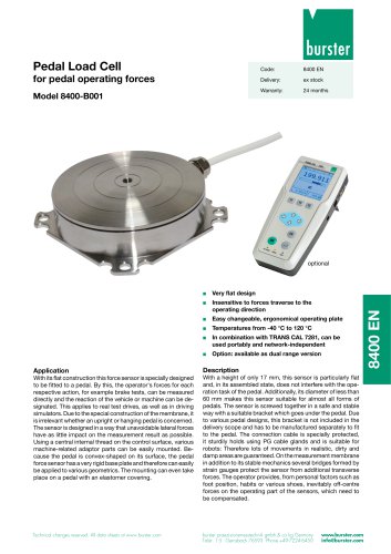 Data Sheet Model 8400-B001
2 Pages
 Load-cell
25 Pages
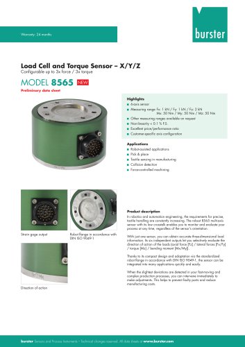 Data Sheet Motel 8565 (2025)
5 Pages
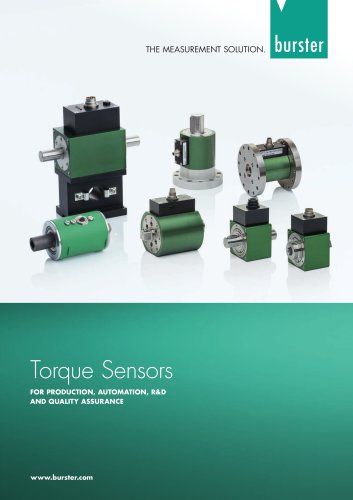 Torque Sensors
9 Pages
 Data Sheet Typ 8625
7 Pages
 Data Sheet Typ 8512 (2025)
5 Pages
 Data Sheet Model 8511 (2025)
6 Pages
 Data Sheet Model 8415 (2025)
6 Pages
 Data sheet Model 8435 (2025)
7 Pages
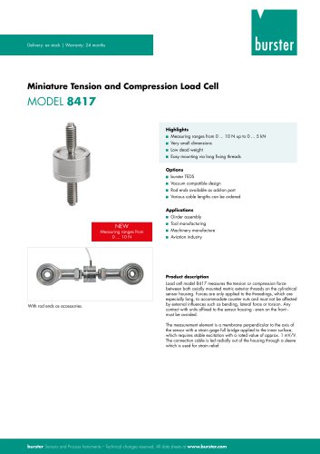 Data Sheet Typ 8417 (2025)
7 Pages
 Data Sheet Typ 8532 (2025)
2 Pages
 Data Sheet 8427 (2025)
7 Pages
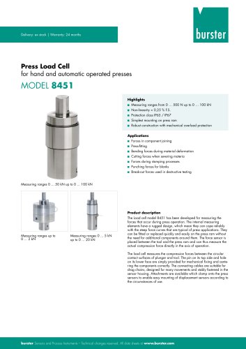 Data Sheet Motel 8451 (2025)
7 Pages
 Data Sheet Model 8527 (2025)
7 Pages
 Data Sheet Model 8526 (2025)
9 Pages
 Flyer Load Experts 2025
1 Page
 Data sheet Typ 8416 (2025)
6 Pages
 Data Sheet Model 8402 (2025)
6 Pages
 2511 BATTERY MEASURING MODULE
14 Pages
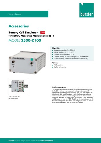 Data Sheet- Model 2500-Z100
2 Pages
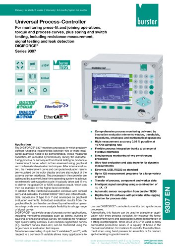 Data Sheet Typ 9307
6 Pages
 Data Sheet Model 9210
5 Pages
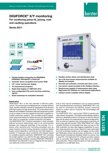 Data Sheet Typ 9311
6 Pages
 Data Sheet Typ 8655 (2025)
7 Pages
 Displacement Sensors 2025
2 Pages
 Data sheet Model 8709 (2025)
2 Pages
 Data sheet Model 8709
2 Pages
 Data Sheet Typ 8655
7 Pages
 Data Sheet Model 8524
8 Pages
 Data Sheet Motel 8451
7 Pages
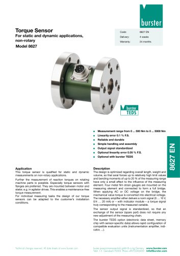 Data Sheet Typ 8627
2 Pages
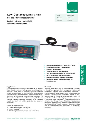
 Data Sheet Model 9186/8532
2 Pages
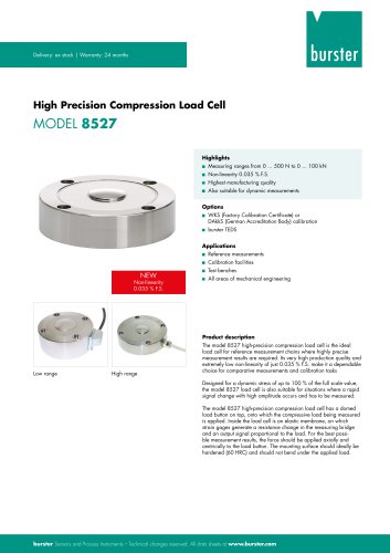 Data Sheet Model 8527
7 Pages
 Data Sheet Typ 8512
5 Pages
 Data Sheet Model 8511
6 Pages
 Data Sheet Typ 8625
7 Pages
 Data Sheet Motel 8565
5 Pages
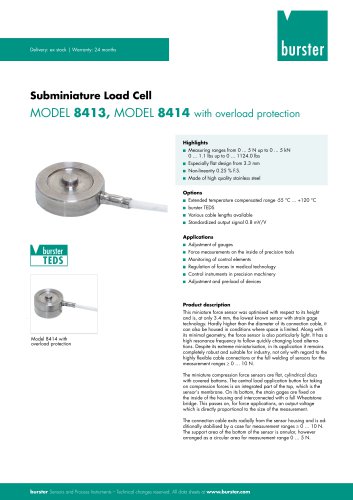
 Data Sheet Typ 8532
2 Pages
 Data Sheet Model 8561
6 Pages
 Data Sheet Model 8510
5 Pages
 Data Sheet Model 8523
8 Pages
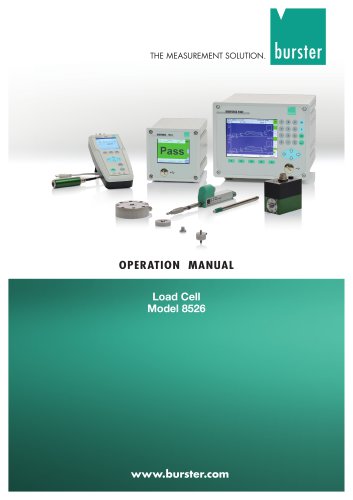
 Data Sheet Model 8526
9 Pages
 Data Sheet Typ 8417
7 Pages
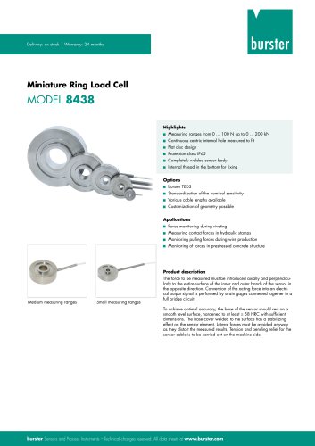 Data Sheet - Model 8438
6 Pages
 Data sheet Model 8435
7 Pages
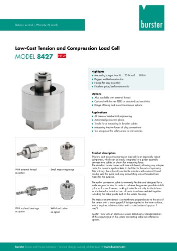 Data Sheet 8427
7 Pages
 Data Sheet Model 8402
6 Pages
 Data sheet Typ 8416
6 Pages
 Press fitting - the reliable way
11 Pages
 Data Sheet Model 9243
2 Pages
 Displacement Sensors
2 Pages
 Flyer Load Experts
1 Page
 Sensor Solutions
1 Page
 Data Sheet Model 9235
2 Pages
 Data sheet Series 8738
2 Pages
 Flyer Battery Tester
1 Page
 Data Sheet Model 2560
5 Pages
 Operation manual
76 Pages
 Data Sheet Typ 8739
2 Pages
 RESISTOMAT® Model 2329
4 Pages
 Data Sheet Model 2550
4 Pages
 Data Sheet Typ 8645
5 Pages
 Flyer Displacement Sensor
2 Pages
 Data Sheet - Model 8670
4 Pages


Archived catalogs
 Data Sheet Model 8415
6 Pages

- Display module
- BURSTER load cell
- Pressure transmitter
- BURSTER tension/compression load cell
- BURSTER steel load cell
- Calibration system
- Analog pressure transmitter
- BURSTER strain gauge load cell
- Digital indicator
- BURSTER stainless steel load cell
- Waterproof pressure transmitter
- Membrane pressure transmitter
- Stainless steel pressure transmitter
- Panel panel meter
- Relative pressure transmitter
- Position transducer
- Signal amplifying integrated circuit
- Beam type force sensor
- BURSTER compression load cell
- Automated software