
- Catalogs
- burster Measurement Solutions GmbH
- Operation Manual Torque sensor Model 8661

Operation Manual Torque sensor Model 8661

Operation Manual Torque sensor Model 8661
The document emphasizes the importance of understanding safety symbols and pictograms, adhering to signal words like DANGER, WARNING, and CAUTION to prevent injury or equipment damage. It highlights risks such as electric shock and advises using the sensor in non-safety-critical applications outside explosive areas.
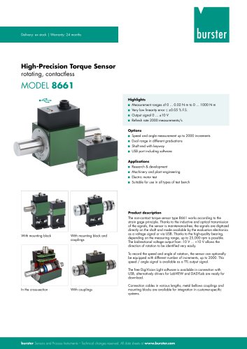
The torque sensor model 8661 is designed for measuring static and dynamic torques on rotating or stationary machine parts. It features contactless transmission and is maintenance-free. The sensor is not intended for safety-critical applications and should be used only for measuring torque, rotational speed, or angular displacement.
The sensor should be protected from moisture, chemicals, and dust, stored in a dry atmosphere with temperatures between 0°C and 60°C, and cleaned with a dry cloth.
The torque sensor consists of a measuring shaft, electronics box, and sensor unit. It operates by deforming the torsion shaft, changing the resistance of strain gauges, which is processed into an analog voltage proportional to the measured torque.
Dynamic torques should be measured at a maximum of 70% of the rated torque to avoid resonance, which can cause damage. Signal analysis and control systems must be considered during dynamic testing.
The manufacturer provides a 24-month warranty, excluding damage from improper use. Regular checks and recalibration are recommended, with bearings replaced after 20,000 hours of operation. Unauthorized modifications void the warranty.
Contact the service department with the serial number for repairs or inquiries. Contact details for burster präzisionsmesstechnik gmbh & co. kg are provided.
Static torque calibration is applicable for dynamic torque measurements, considering the instrumentation amplifier's characteristics. The resonant frequency is determined by the sensor's spring constant and the moments of inertia of connected bodies. The Holzer-Tolle method is suggested for determining resonant frequency.
Potential interference sources include temperature changes, vibrations, spurious forces, electromagnetic and magnetic interference, and misalignments. Measures should be taken to mitigate these interferences for accurate measurements.
Preparation: A run-in period is recommended before installation to distribute lubricant evenly. Proper shaft fit and clean mounting surfaces are essential.
Mechanical Installation: Detailed instructions are provided for installing the torque sensor using a mounting block or free-floating installation, emphasizing avoiding excessive torques and ensuring precise alignment.
The torque sensor model 8661 requires a specific power supply setup, with caution against connecting power via multiple connections simultaneously. Connector pin assignments and guidance on voltage output for torque and TTL output for rotational speed are detailed.
Proper cable management is crucial to avoid interference from electrical and magnetic fields. Recommendations include grounding the sensor, using shielded cables, and maintaining a safe distance from high-energy equipment.
The procedure for switching on the torque sensor is outlined, noting that some models perform a self-test upon startup. The importance of using appropriate extension cables and adjusting the measuring chain if necessary is emphasized.
Status Display: LED indicators display torque levels, with different colors indicating various torque ranges and faults.
Speed Limits: Adhering to specified speed limits is crucial to prevent damage.
Check Function: Applying a voltage to the test input should result in a 10.000 V output signal.
USB Version: Requires careful handling of the protective dust cap and proper connection to a computer. It identifies as a high power device, drawing 495 mA, which may require an active USB hub for laptops.
This software is necessary for configuring and analyzing data from the torque sensor. It supports up to 32 measurement channels and allows for extensive parameter configuration. The software requires a valid license key for use.
Users can configure dimensional units, conversion factors, and measurement ranges. Limits and properties such as software version and calibration date can also be set.
Users can select measurement rates and modes, including normal and speed-optimized polling mode (SPOM), and configure display settings for measurement curves.
DigiVision provides tools for saving, viewing, and exporting measurement reports. Reports can be exported to Excel or printed as PDF documents.
The software is compatible with various Windows operating systems and requires a minimum of 256 MB RAM and 500 MB of free hard disk space.
Administrative rights are required to install DigiVision. The installation involves running "autorun.exe" from the CD-ROM, choosing a language, and proceeding with the setup. If .NET Framework 4.0 is not installed, it will be installed automatically.
Connect the USB cable to the torque sensor and a USB port on the PC. Update the driver software by specifying the path to the driver files located in the DigiVision installation directory.
Enable "Save raw-data measurement files" in DigiVision preferences to store measurement data.
Different versions of the software offer varying capabilities, from a free version with 1-channel measurement to an upgradeable version with 32-channel measurement. Activation is done via an activation code.
Angle/Speed Measurement: The sensor can include angle/speed measurement with various encoder disk increments.
Dual-Range Sensor: Allows measurement over two ranges with specific voltage levels for switching.
Factory calibration includes measurement values, uncertainty, and traceability. DAkkS calibration follows ISO-17025 standards. Regular recalibration is recommended every 12 months or after specific events like overload or repair.
Properly remove and protect the torque sensor from physical damage.
The technical specifications for the sensor model 8661 can be found in the enclosed data sheet, accessible online.
Interference Immunity: Complies with EN 61326-2-3:2006 for industrial locations.
Emitted Interference: Also adheres to EN 61326-2-3:2006 standards.
Detailed information about accessories, including the DigiVision configuration and analysis software, is available in the data sheet online.
Battery Disposal: Users are legally required to return used batteries and rechargeable batteries, as disposal through household waste is prohibited.
Equipment Disposal: Unserviceable equipment must be disposed of in accordance with legal requirements to contribute to environmental protection.
Catalog excerpts
OPERATION MANUALTorque sensor Model 8661 Manufacturer: burster burster praezisionsmesstechnik gmbh & co kg praezisionsmesstechnik gmbh & co kg All rights reserved Talstr. 1 - 5 P.O. 1432 Germany Germany Valid from: Fax.: +49-7224-645-88 Email: [email protected] www.burster.com
Open the catalog to page 1
Exclusion of warranty liability for operating manuals All information in the present documentation was prepared and compiled with great care and reproduced subject to effective control measures. No warranty is provided for freedom from errors. We reserve the right to make technical changes. The present information as well as the corresponding technical data can change without notice. Reproduction of any part of this documentation or its processing or revision using electronic systems is prohibited without the manufacturer‘s prior written approval. Components, devices and measured value sensors...
Open the catalog to page 2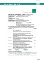
The measurement solution. EU-Konformitatserklarung (nach en iso/iec 17050-1:2010) Issuer's name: burster prazisionsmesstechnik gmbh & co kg Prazisions-Drehmomentsensor + Steckernetzteil Precision Torque Sensor + power pack Modellnummer(n) (Typ): Model number/ type: Diese Erklarung beinhaltet obengenannte Produkte mit alien Optionen This declaration covers all options of the above product(s) The object of the declaration described above is in conformity with the requirements of the following documents: Richtlinie zur Beschrankung der Verwendung bestimmter gefahrlicher Stoffe in Elektro- und Elektronikgeraten...
Open the catalog to page 3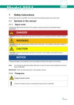
On the torque sensor model 8661 and in this manual the following symbols warn about risks. 1.1 Symbols in this manual The following signal words are used in the operation manual according to the specified hazard classification. DANGER DANGER indicates a hazard with a high level of risk which, if not avoided, will result in death or serious injury. WARNING indicates a hazard with a medium level of risk which, if not avoided, could result in death or serious injury. CAUTION indicates a hazard with a low level or risk which, if not avoided, could result in minor or moderate injury. Property damage...
Open the catalog to page 7
General safety instructions The torque sensor model 8661 uses state-of-the-art engineering and is safe to operate. However, if the torque sensor model 8661 is not used or operated as intended, it may present a hazard. DANGER Danger of electric shock! The following instructions must be followed to prevent electric shock and injuries: • In order to achieve high measuring characteristic value, the torque sensor model 8661 is not designed with the usual safety factors (2…20) for machine designs. For applicable overload factors, see the technical data (data sheet). • Observe accident prevention regulations,...
Open the catalog to page 8
IMPORTANT: Read the operation manual carefully before using the equipment, and keep for future reference. The torque sensor model 8661 measures static and dynamic torques on rotating or stationary machine parts in either direction of rotation. You have the option of measuring rotational speed or angular displacement. The respective upper range value is shown on the type plate. The USB version of the 8661 torque sensor model 8661 transmits all measurement signals via USB. Both the low mass of the torque sensor model 8661 and its high torsional rigidity are an advantage when measuring dynamic torques....
Open the catalog to page 9
2.3 Environmental conditions • Avoid radiant heat or cooling from one side. • Protect the torque sensor model 8661 from moisture. • The torque sensor model 8661 is not resistant to the effects of chemicals. Do not use the torque sensor model 8661 in a corrosive environment. • Keep the bearings and connectors free of dust, dirt and other foreign matter. Use clean packaging to package the torque sensor model 8661. The torque sensor model 8661 must be stored under the following conditions: A DANGER Electric shock hazard! Disconnect the torque sensor model 8661 from the electrical supply before cleaning....
Open the catalog to page 10
• Torque sensor model 8661 • Mating connector • Operation manual • Data sheet DANGER Electric shock hazard! Never connect up the torque sensor model 8661 if it shows signs of damage incurred in transit. Only ever use the torque sensor model 8661 under the conditions specified in this operation manual. Inspect the torque sensor model 8661 carefully for damage. If you suspect that the torque sensor model 8661 has been damaged during shipping, notify the delivery company within 72 hours. The packaging should be retained for examination by a representative of the manufacturer and/or the delivery...
Open the catalog to page 11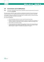
2.8 Conversions and modifications Note: If you open or dismantle the torque sensor model 8661 during the warranty period, this will void The torque sensor model 8661 does not contain any parts that are intended to be serviced by the user. Only the manufacturer's own qualified personnel are permitted to open the torque sensor model 8661. It is forbidden to make any modification to the torque sensor model 8661 without our written permission. We cannot accept liability in the event of such action. • Check the bearings at least once a year to see that they still move freely. • Replace the special...
Open the catalog to page 12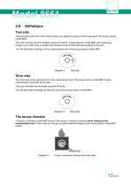
Test side The test side is that end of the shaft at which you apply the torque being measured to the torque sensor model 8661. This side normally has the smallest moment of inertia. Torque sensors model 8661 with measuring ranges up to 2 Nm have a smaller and therefore lower-friction ball bearing fitted at this end. You will see these markings on the measurement end of the torque sensor model 8661: Test side Drive side The drive side is the opposite end to the measurement end. The torque sensor model 8661 is also mechanically connected at this side. This side normally has the larger moment of...
Open the catalog to page 13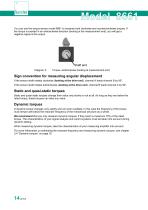
You can use the torque sensor model 8661 to measure both clockwise and counterclockwise torques. If the torque is exerted in an anticlockwise direction (looking at the measurement end), you will get a negative signal at the output. Torque, anticlockwise (looking at measurement end) Sign convention for measuring angular displacement If the sensor shaft rotates clockwise (looking at the drive end), channel A leads channel B by 90°. If the sensor shaft rotates anticlockwise (looking at the drive end), channel B leads channel A by 90°. Static and quasi-static torques Static and quasi-static torques...
Open the catalog to page 14All Burster Measurement Solutions GmbH catalogs and technical brochures
 Operation Manual Model 8565
24 Pages
 Data Sheet Model 8744
6 Pages
 Data Sheet Model 8742
6 Pages
 Data Sheet Model 7281
5 Pages
 Data Sheet Model 9250
7 Pages
 Operation manual 2025
76 Pages
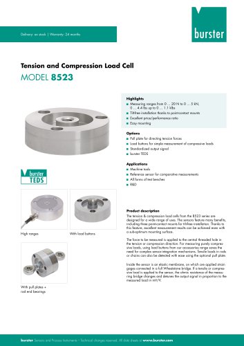 Data Sheet Model 8523 (2025)
8 Pages
 Data-Sheet- Model 8228
6 Pages
 Data Sheet Model 8656
7 Pages
 Brochure Load Cell
25 Pages
 Data Sheet Model 8510 (2025)
5 Pages
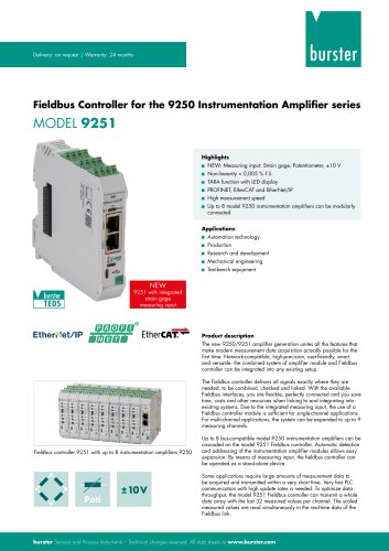 Data-Sheet - 9251
6 Pages
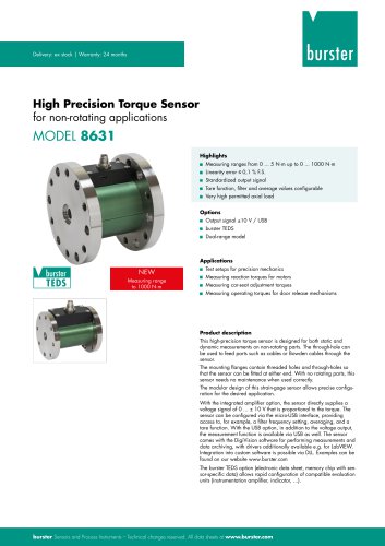 Data sheet Model 8631
5 Pages
 Data Sheet Model 2511
6 Pages
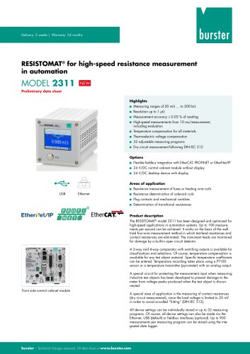 Data Sheet Model 2311
5 Pages
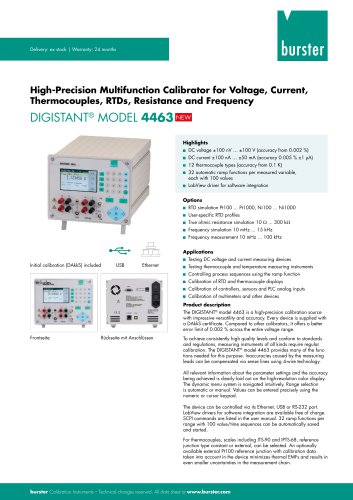 Data Sheet Model 4463
5 Pages
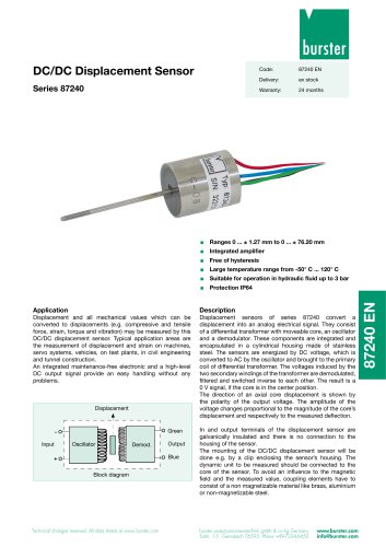 Data Sheet Typ 87240
2 Pages
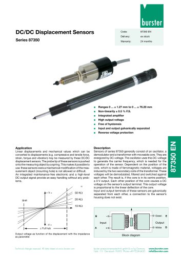 Data Sheet Series 87350
2 Pages
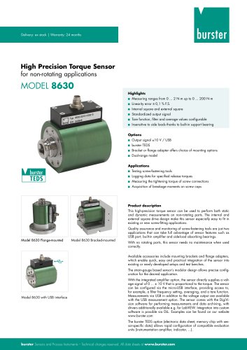 Data Sheet Model 8630
6 Pages
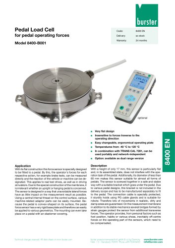 Data Sheet Model 8400-B001
2 Pages
 Load-cell
25 Pages
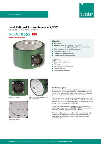 Data Sheet Model 8565
5 Pages
 Torque Sensors
9 Pages
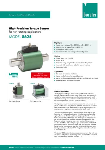 Data Sheet Typ 8625
7 Pages
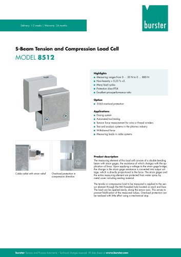 Data Sheet Typ 8512 (2025)
5 Pages
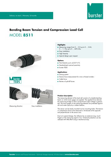 Data Sheet Model 8511 (2025)
6 Pages
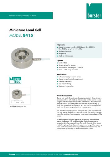 Data Sheet Model 8415 (2025)
6 Pages
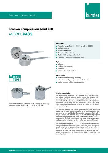 Data sheet Model 8435 (2025)
7 Pages
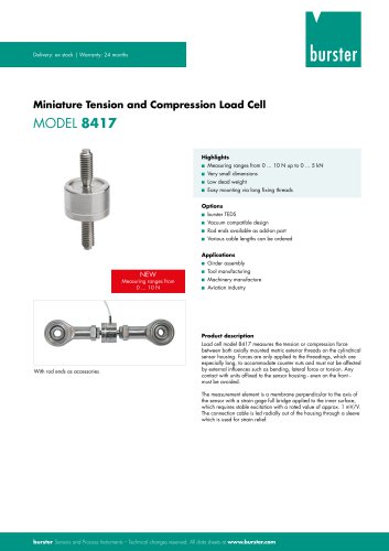 Data Sheet Typ 8417 (2025)
7 Pages
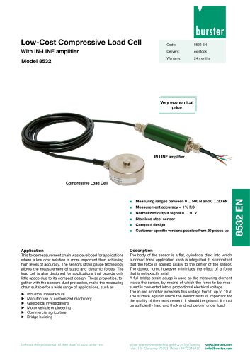 Data Sheet Typ 8532 (2025)
2 Pages
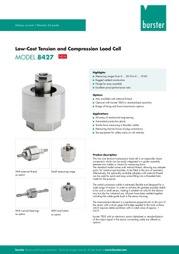 Data Sheet 8427 (2025)
7 Pages
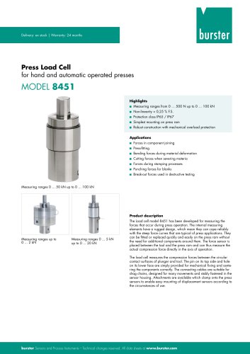 Data Sheet Motel 8451 (2025)
7 Pages
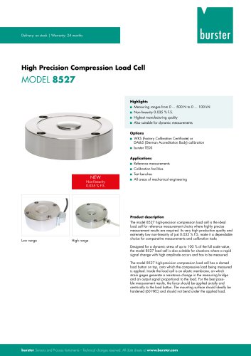 Data Sheet Model 8527 (2025)
7 Pages
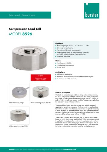 Data Sheet Model 8526 (2025)
9 Pages
 Flyer Load Experts 2025
1 Page
 Data sheet Typ 8416 (2025)
6 Pages
 Data Sheet Model 8402 (2025)
6 Pages
 2511 BATTERY MEASURING MODULE
14 Pages
 Data Sheet- Model 2500-Z100
2 Pages
 Data Sheet Typ 9307
6 Pages
 Data Sheet Model 9210
5 Pages
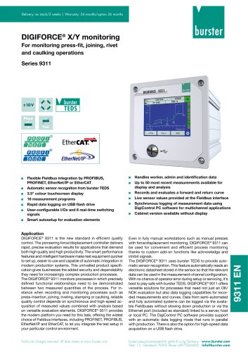 Data Sheet Typ 9311
6 Pages
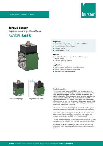 Data Sheet Typ 8655 (2025)
7 Pages
 Displacement Sensors 2025
2 Pages
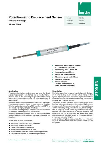 Data sheet Model 8709 (2025)
2 Pages
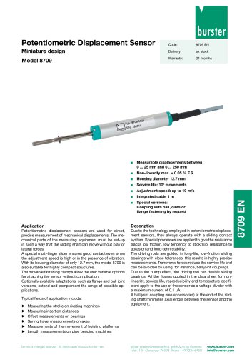 Data sheet Model 8709
2 Pages
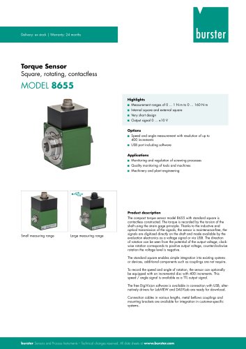 Data Sheet Typ 8655
7 Pages
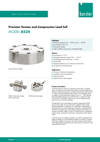 Data Sheet Model 8524
8 Pages
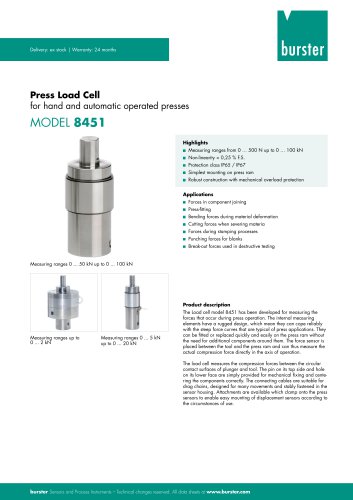 Data Sheet Motel 8451
7 Pages
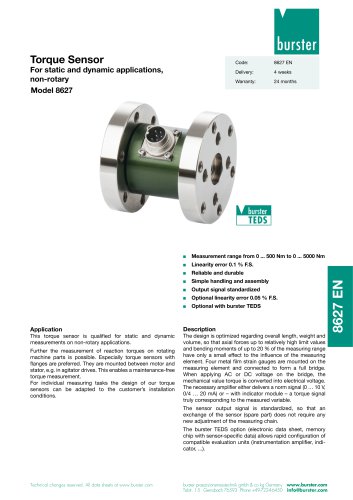 Data Sheet Typ 8627
2 Pages
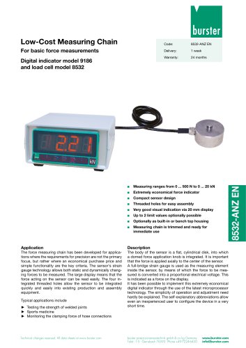 Data Sheet Model 9186/8532
2 Pages
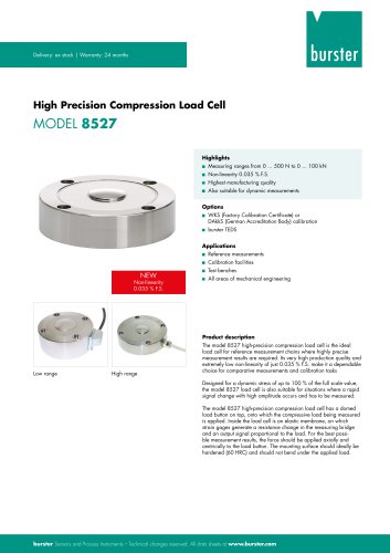 Data Sheet Model 8527
7 Pages
 Data Sheet Typ 8512
5 Pages
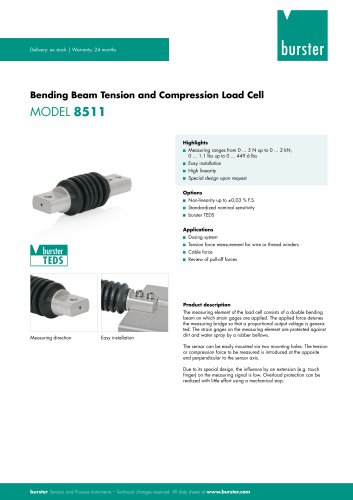 Data Sheet Model 8511
6 Pages
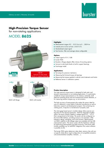 Data Sheet Typ 8625
7 Pages
 Data Sheet Typ 8532
2 Pages
 Data Sheet Model 8561
6 Pages
 Data Sheet Model 8510
5 Pages
 Data Sheet Model 8523
8 Pages
 Data Sheet Model 8526
9 Pages
 Data Sheet Typ 8417
7 Pages
 Data Sheet - Model 8438
6 Pages
 Data sheet Model 8435
7 Pages
 Data Sheet 8427
7 Pages
 Data Sheet Model 8402
6 Pages
 Data sheet Typ 8416
6 Pages
 Press fitting - the reliable way
11 Pages
 Data Sheet Model 9243
2 Pages
 Displacement Sensors
2 Pages
 Flyer Load Experts
1 Page
 Sensor Solutions
1 Page
 Data Sheet Model 9235
2 Pages
 Data sheet Series 8738
2 Pages
 Flyer Battery Tester
1 Page
 Data Sheet Model 2560
5 Pages
 Operation manual
76 Pages
 Data Sheet Typ 8739
2 Pages
 RESISTOMAT® Model 2329
4 Pages
 Data Sheet Model 2550
4 Pages
 Data Sheet Typ 8645
5 Pages
 Flyer Displacement Sensor
2 Pages
 Data Sheet - Model 8670
4 Pages

























Archived catalogs
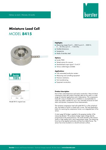 Data Sheet Model 8415
6 Pages

- BURSTER load cell
- Pressure transmitter
- BURSTER tension/compression load cell
- BURSTER steel load cell
- Calibration system
- Analog pressure transmitter
- BURSTER strain gauge load cell
- Digital indicator
- BURSTER stainless steel load cell
- Waterproof pressure transmitter
- Membrane pressure transmitter
- Stainless steel pressure transmitter
- Panel panel meter
- Relative pressure transmitter
- Position transducer
- Beam type force sensor
- Signal amplifying integrated circuit
- BURSTER compression load cell
- Automated software