
- Catalogs
- burster Measurement Solutions GmbH
- Operation Manual RESISTOMAT® Type 2304 (2025)

Operation Manual RESISTOMAT® Type 2304 (2025)
Operation Manual RESISTOMAT® Type 2304 (2025)
Catalog excerpts

OPERATION MANUALRESISTOMAT® Type 2304 Manufacturer: prazisionsmesstechnik gmbh & co kg All rights reserved burster prazisionsmesstechnik gmbh & co kg TalstraBe 1 - 5 P.O.Box 1432 Germany Germany E-Mail: [email protected] www.burster.de
Open the catalog to page 1
Techn. Specifications & Appendix Note: Exclusion of warranty liability for operating manuals All information in the present documentation was prepared and compiled with great care and reproduced subject to effective control measures. No warranty is provided for freedom from errors. We reserve the right to make technical changes. The present information as well as the corresponding technical data can change without notice. Reproduction of any part of this documentation or its processing or revision using electronic systems is prohibited without the manufacturer’s prior written approval. Components,...
Open the catalog to page 2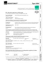
EG-Konformitätserklärung Operation EC- Declaration of Conformity according to EN ISO/IEC 17050-1:2004 burster präzisionsmesstechnik gmbh & co kg Name des Herstellers: Manufacturer’s Name: Talstr. 1-5 76593 Gernsbach, Germany Adresse des Herstellers: Manufacturer’s Address: declares under sole responsibility that the product as originally delivered Hochpräziser Meß- und Prüfautomat für die elektrische Widerstandsmeßtechnik Product Name: High-Precision Automatic Inspection and Test Unit for Electrical Resistance Testing Models Number / Type: Diese Erklärung beinhaltet obengenannte Produkte mit...
Open the catalog to page 3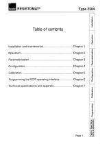
tions'k Aplsendfx Programming Calibration Configuration Parameterization Operation installation
Open the catalog to page 5
Position the RESISTOMAT® resistance measuring device so that enough space is left behind the back panel to ensure proper ventilation of the black heat sink. The output of the ventilation channel shown in Fig. 1.2 must not be obstructed. Enough space should also be allowed for the connection of interface cables. The device weighs 28 kg and is contained in appropriately shock-resistant packaging. Unpack it carefully and check whether any contents are missing. The standard scope of delivery includes: - a type 2304 resistance measuring device, - a copy of this handbook. Check the device carefully...
Open the catalog to page 13
Optional features and accessories - Version for 115VAC + 6% -10% power line voltage. - Type 2304-Z004 calibration resistance package: 5 type 1240 calibration resistances with values of 1OO^tQ, 1 mQ, 10 mQ, 100 mQ and 1 Q. Every resistance has a DKD (german calibration service) label.ln addition, every package contains a type 2394 adapter for direct connection of the calibration resistances to the measurement sockets of the RESISTOMAT® (see Chap. 2.4.5). - Temperature measuring sensor (Ptl 00) including LEM01B type 2304-V001 plug connector: For measuring the temperature of the test unit in the...
Open the catalog to page 15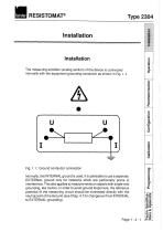
Installation Installation The measuring amplifier (analog section) of the device is connected internally with the equipment grounding conductor as shown in Fig. 1.1. Normally, this INTERNAL ground is used. It is advisable to use a separate, EXTERNAL ground only for networks which are particularly prone to interference. This also applies to measurements on objects with single-end grounding, like motors. In order to avoid ground loops here, the reference potential of the measuring circuit should be connected directly with the neutral point of the test unit.(see Chap. 4.7 for changeover from INTERNAL...
Open the catalog to page 17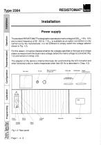
Installation Power supply s .!? -W The standard RESISTOMAT@isdesigned to operateat a mains voltageof 230„ + 6%- 10% and a mains frequency of 45 - 65 Hz. 115„, is available as an option (conversion is only carried out by the manufacturer; it is not sufficient to simply switch the voltage selector shown in Fig. 1.2). For this reason, it must be checked whether the voltages specified on the type and voltage plates correspond with the local mains voltage, before the mains voltage is connected (Fig. 1.2) and turned on (Chap. 2.2). The adaption of the device's internal time base (for synchronizing...
Open the catalog to page 18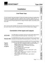
Installation Line Power fuse s The two line power fuses each rated at 2 A (both with medium time-lag) are located behind the panel with the voltage inforrnation, inside the mains connection module (see Fig. 1.2). The fuses are changed by inserting a screwdriver into the notch underneath the upper edge of the mains socket, lifting the plate with the voltage information slightly, and pulling out the fuse-insert. ATTENTION: After a fuse has been changed, the fuse-insert must be pushed into the mains module in the correct manner (mark on housing facing arrow with the desired mains voltage). Connection...
Open the catalog to page 19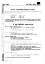
Type 2304 RESISTOMAT® Sns^ Ap^endfx Programming Calibration Configuration Parameterization Operation Installation Device address for computer control The device address can be selected via a keyboard or an external interface. The following chapters contain the relevant information: The address selected last is stored after the mains voltage is turned off; the factory presettings (see Chap. 7.4) are "9" (IEC bus) and ”0" (group and device address in the case of RS 232/485). Removing the upper and lower casings: - Loosen the fastening screws (4 each at the top and bottom), - remove the 8 clamping...
Open the catalog to page 20
Maintenance General Information In principle, the RESISTOMAT does not require any maintenance by the user. If any repairwork becomes necessary, it must only be carried out by the manufacturer. The device complies with the relevant VDE (Associaton of German Engineers) specifications and postal interference suppression regulations. Enquiries Shipping Customer service The manufacturer strongly recommends accompanying technical enquires with the relevant serial numbers. Only then is it possible to determine the technical model (including the software version) and thus ensure a prompt solution. The...
Open the catalog to page 21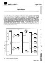
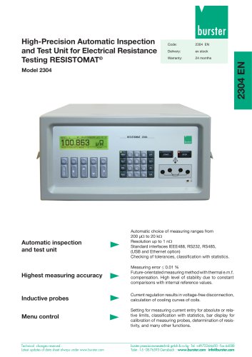
Operation The measuring unit of the high-precision RESISTOMAT® 2304 automatic measuring and testing device operates on the principle of an advanced 4-wire design shown in Fig. 1.3. The voltage drops when current is applied are measured not only across the test unit, but also across an internal reference resistor. Both voltage drops are used to calculate the quotient, which is multiplied by the characteristic value of the reference resistor in order to determine the ohmic value of the test unit. This procedure eliminates contact and transition resistances and is advantageous in that measurement...
Open the catalog to page 23All Burster Measurement Solutions GmbH catalogs and technical brochures
 Operation Manual Model 8565
24 Pages
 Data Sheet Model 8744
6 Pages
 Data Sheet Model 8742
6 Pages
 Data Sheet Model 7281
5 Pages
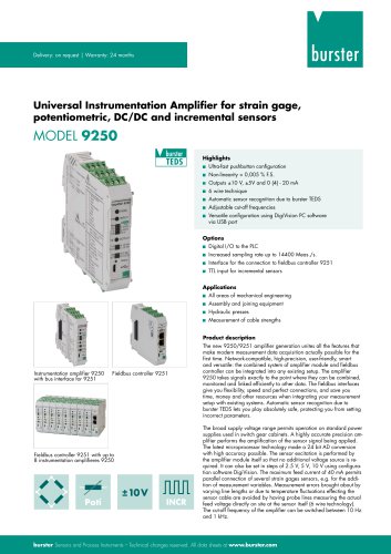 Data Sheet Model 9250
7 Pages
 Operation manual 2025
76 Pages
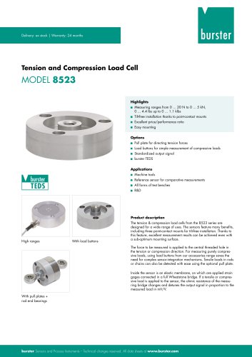 Data Sheet Model 8523 (2025)
8 Pages
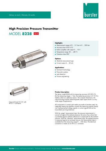 Data-Sheet- Model 8228
6 Pages
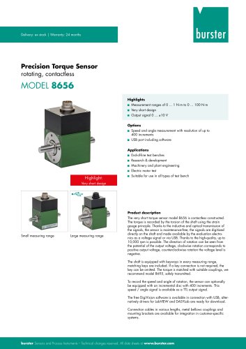 Data Sheet Model 8656
7 Pages
 Brochure Load Cell
25 Pages
 Data Sheet Model 8510 (2025)
5 Pages
 Data-Sheet - 9251
6 Pages
 Data sheet Model 8631
5 Pages
 Data Sheet Model 2511
6 Pages
 Data Sheet Model 2311
5 Pages
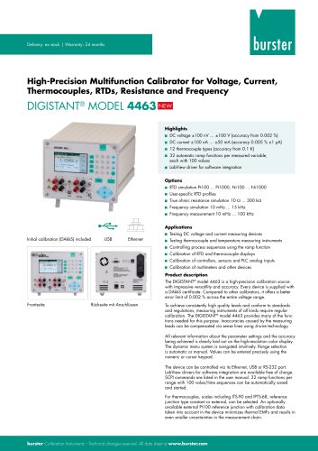 Data Sheet Model 4463
5 Pages
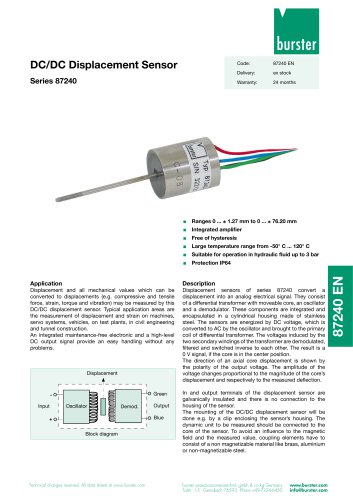 Data Sheet Typ 87240
2 Pages
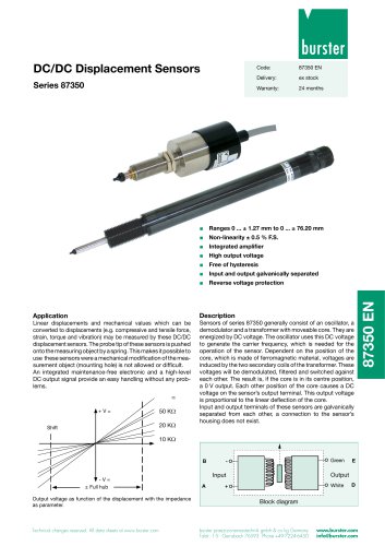 Data Sheet Series 87350
2 Pages
 Data Sheet Model 8630
6 Pages
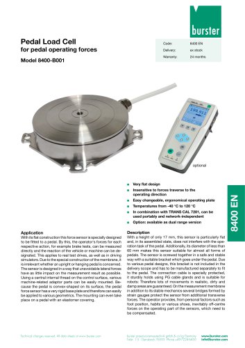 Data Sheet Model 8400-B001
2 Pages
 Load-cell
25 Pages
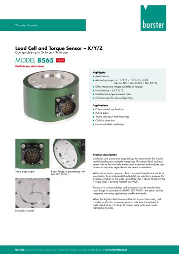 Data Sheet Model 8565
5 Pages
 Torque Sensors
9 Pages
 Data Sheet Typ 8625
7 Pages
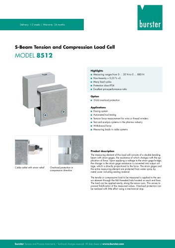 Data Sheet Typ 8512 (2025)
5 Pages
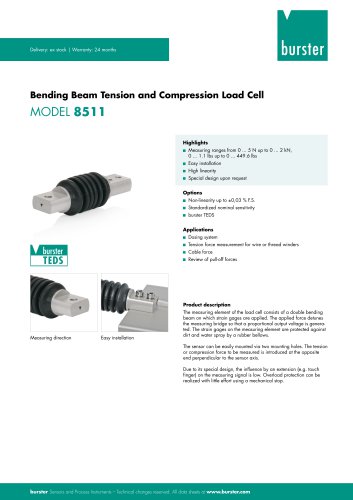 Data Sheet Model 8511 (2025)
6 Pages
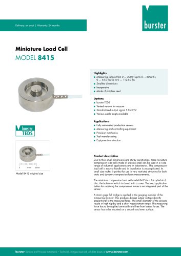 Data Sheet Model 8415 (2025)
6 Pages
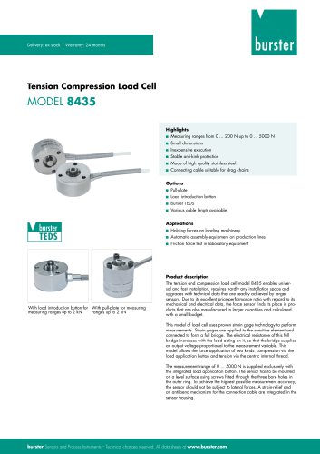 Data sheet Model 8435 (2025)
7 Pages
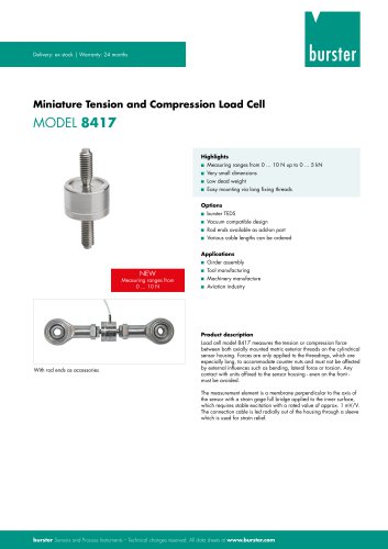 Data Sheet Typ 8417 (2025)
7 Pages
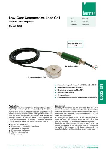 Data Sheet Typ 8532 (2025)
2 Pages
 Data Sheet 8427 (2025)
7 Pages
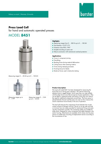 Data Sheet Motel 8451 (2025)
7 Pages
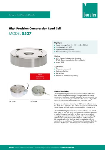 Data Sheet Model 8527 (2025)
7 Pages
 Data Sheet Model 8526 (2025)
9 Pages
 Flyer Load Experts 2025
1 Page
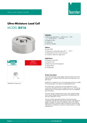 Data sheet Typ 8416 (2025)
6 Pages
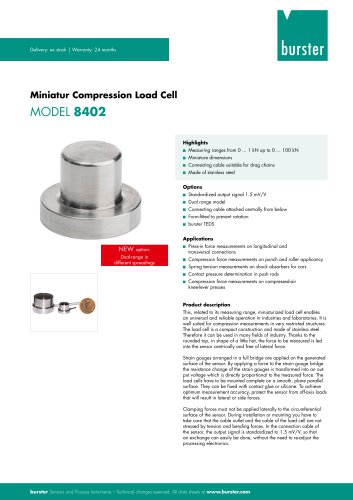 Data Sheet Model 8402 (2025)
6 Pages
 2511 BATTERY MEASURING MODULE
14 Pages
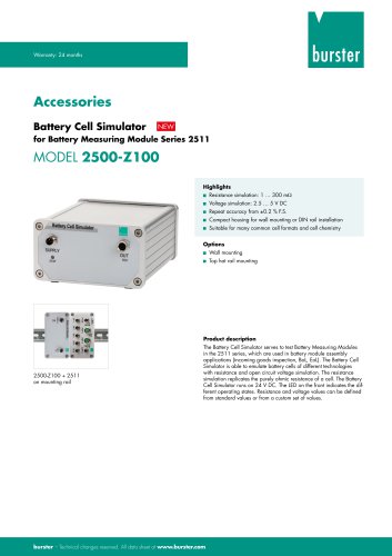 Data Sheet- Model 2500-Z100
2 Pages
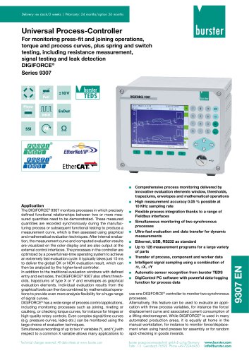 Data Sheet Typ 9307
6 Pages
 Data Sheet Model 9210
5 Pages
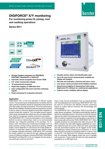 Data Sheet Typ 9311
6 Pages
 Data Sheet Typ 8655 (2025)
7 Pages
 Displacement Sensors 2025
2 Pages
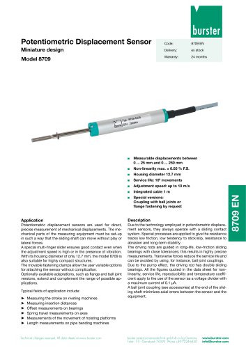 Data sheet Model 8709 (2025)
2 Pages
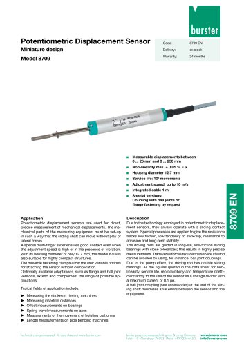 Data sheet Model 8709
2 Pages
 Data Sheet Typ 8655
7 Pages
 Data Sheet Model 8524
8 Pages
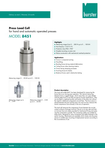 Data Sheet Motel 8451
7 Pages
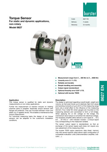 Data Sheet Typ 8627
2 Pages
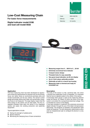 Data Sheet Model 9186/8532
2 Pages
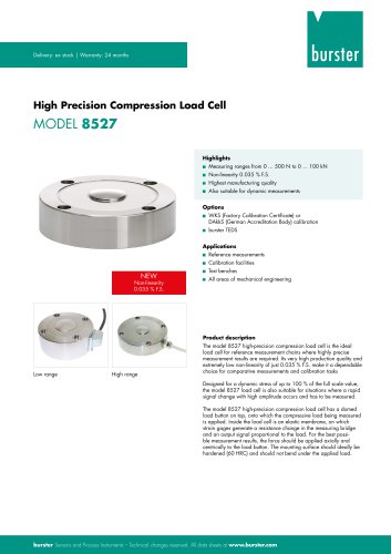 Data Sheet Model 8527
7 Pages
 Data Sheet Typ 8512
5 Pages
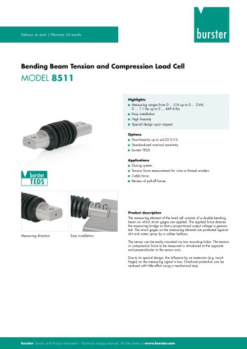 Data Sheet Model 8511
6 Pages
 Data Sheet Typ 8625
7 Pages
 Data Sheet Typ 8532
2 Pages
 Data Sheet Model 8561
6 Pages
 Data Sheet Model 8510
5 Pages
 Data Sheet Model 8523
8 Pages
 Data Sheet Model 8526
9 Pages
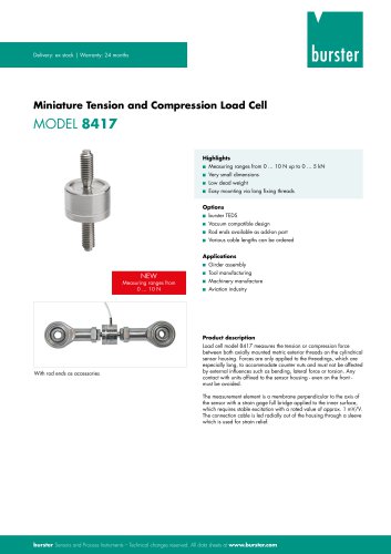 Data Sheet Typ 8417
7 Pages
 Data Sheet - Model 8438
6 Pages
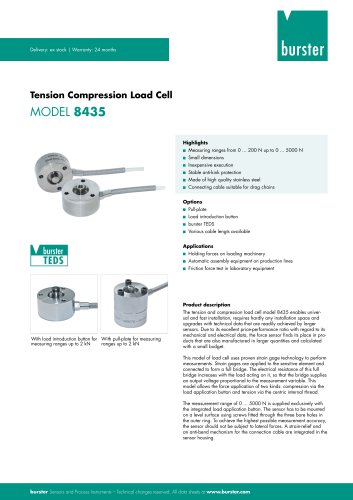 Data sheet Model 8435
7 Pages
 Data Sheet 8427
7 Pages
 Data Sheet Model 8402
6 Pages
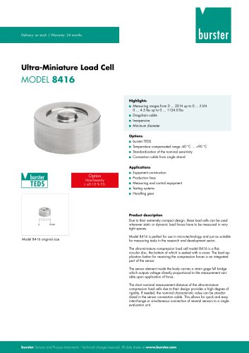 Data sheet Typ 8416
6 Pages
 Press fitting - the reliable way
11 Pages
 Data Sheet Model 9243
2 Pages
 Displacement Sensors
2 Pages
 Flyer Load Experts
1 Page
 Sensor Solutions
1 Page
 Data Sheet Model 9235
2 Pages
 Data sheet Series 8738
2 Pages
 Flyer Battery Tester
1 Page
 Data Sheet Model 2560
5 Pages
 Operation manual
76 Pages
 Data Sheet Typ 8739
2 Pages
 RESISTOMAT® Model 2329
4 Pages
 Data Sheet Model 2550
4 Pages
 Data Sheet Typ 8645
5 Pages
 Flyer Displacement Sensor
2 Pages
 Data Sheet - Model 8670
4 Pages


































Archived catalogs
 Data Sheet Model 8415
6 Pages

- BURSTER load cell
- Pressure transmitter
- BURSTER tension/compression load cell
- BURSTER steel load cell
- Calibration system
- Analog pressure transmitter
- BURSTER strain gauge load cell
- Digital indicator
- BURSTER stainless steel load cell
- Waterproof pressure transmitter
- Membrane pressure transmitter
- Stainless steel pressure transmitter
- Panel panel meter
- Relative pressure transmitter
- Position transducer
- Beam type force sensor
- Signal amplifying integrated circuit
- BURSTER compression load cell
- Automated software