
- Catalogs
- burster Measurement Solutions GmbH
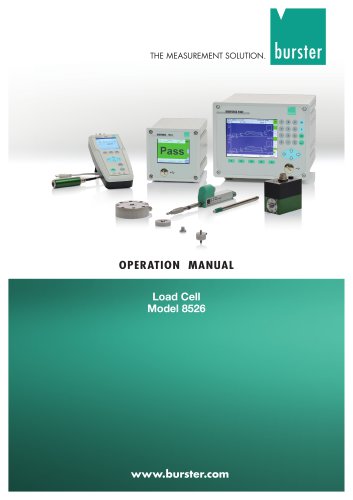
- Operation Manual Load Cell Model 8526

Operation Manual Load Cell Model 8526

Operation Manual Load Cell Model 8526
The Model 8526 load cells are designed for force measurement in production equipment, using Newtons as the unit of measurement. It is important to consider local gravitational acceleration when determining masses.
Unpacking and Initial Setup
Upon receipt, inspect the sensor for any damage and notify the delivery company within 72 hours if damaged. Use original or equivalent packaging for transport. Connect the sensor to instrumentation amplifiers with safety transformers according to EN 61558 standards.
Storage Conditions
Store the sensor in dry conditions without condensation, at temperatures between 0°C and 60°C. No special steps are needed after storage if these conditions are met.
Principle of Operation
The sensor operates using a spring element that deforms elastically under force, with strain gauges converting this deformation into an electrical signal. The spring element is made from high-quality materials used in the aeronautical industry.
Mechanical Design
The 8526 model features a horizontally-mounted elastic membrane with a central load button. Strain gauges are mounted on the underside of the spring element to measure deformation.
Strain Gauge Function and Wiring
Strain gauges increase in electrical resistance when stretched and are connected as a Wheatstone bridge to reduce measurement interference. Compensation and balancing resistors manage temperature effects and balance the circuit.
Installation Guidelines
Mount the sensor on a stable, polished surface without coatings or holes. Apply force centrally and perpendicularly to avoid lateral forces and torques. Do not shorten the sensor cable, and avoid clamping or press-fitting the load cell.
Electrical System and Evaluation
Protect the sensor from fluids and ensure cables have large bend radii to avoid damage. Keep the sensor and cables away from high-energy equipment to prevent electromagnetic interference. Lay measuring lines separately from high-power cables.
Overload Protection
Diaphragms are sensitive to overload; use pressure limiters and avoid sudden force applications. If overloaded, check for changes in the zero-point output signal.
- Adjustment with a Physical Magnitude: Calibrate the sensor using a known physical magnitude, ensuring the entire measuring chain is adjusted. This involves removing any load, adjusting the zero, loading with a reference weight, and adjusting the scale value. Factory calibration certificates can be provided.
- Adjustment Using Test and Calibration Report Data: Depending on the electronics, data from the test report can be directly inserted or simulated using a strain gauge simulator or shunt resistor.
- Shunt Calibration: Use a precision resistor to create an imbalance in the bridge circuit, simulating a specific load. This offset is used to adjust the measurement chain.
- Strain Gauge Simulator Adjustment: Replace the sensor with a simulator to test various output states, ensuring proper function.
- Precision Voltage Source Adjustment: Use a precision voltage source to simulate the sensor, requiring measurement of the supply voltage with a digital voltmeter for accurate calibration.
Burster provides a warranty for material and production defects but excludes liability for improper use or consequential damages. Technical changes may occur without notice, and reproduction of the documentation requires prior approval.
Catalog excerpts

OPERATION MANUAL Load Cell Model 8526
Open the catalog to page 1
In diesem Handbuch finden Sie alle Informationen, die Sie für die Inbetriebnahme und den Betrieb dieses Gerätes benötigen. This operation manual provides you with all information necessary for the set-up and operation of the instrument. Haben Sie wider Erwarten dennoch Probleme, hilft Ihnen der zuständige Produktingenieur weiter. Rufen Sie uns einfach an unter Tel. 07224/645-0 oder unter der auf dem Lieferschein angegebenen Telefon-Durchwahl. Gerne können Sie uns auch eine email mit Ihren offenen Fragen schicken. If, contrary to expectations, you face any problems with the operation of the instrument,...
Open the catalog to page 2
Technical Product Information Commissioning, Function, Fitting Specifications Load Cell Model 8526 1. Introduction The load cells in the model 8526 series are primarily designed for the measurement of force in production equipment, using Newtons (N) as the unit of measurement. The local gravitational acceleration (g ≈ 9.81 m/s²) must be taken into account when determining masses. 2. Preparations for use 2.1 Unpacking Inspect the sensor carefully for damage. If you suspect that the unit has been damaged during shipping, notify the delivery company within 72 hours. Keep all packaging materials...
Open the catalog to page 3
Technical Product Information Commissioning, Function, Fitting Specifications Model 8526 2.4 Storage The sensor must be stored under the following conditions only: • Note: Provided the storage conditions have been observed, no special steps need to be taken after storage and prior to commissioning. 3. Principle of operation The sensor operates with the aid of a spring element. The force to be measured deforms the spring element elastically. This deformation is transformed into an electrical signal by strain gauges. They, together with the spring element, constitute the measuring element of the...
Open the catalog to page 4
Technical Product Information Commissioning, Function, Fitting Specifications Model 8526 This elastic membrane is deflected by the applied force, resulting in a reduction in the sensor’s overall height. This deformation cannot be seen by the naked eye. It is measured by strain gauges. In the 8526 devices, the strain gauges are mounted on the underside of the spring element. This ensures that they are subject to the same deformation as the spring element. 3.3 Function of the strain gauge The electrical resistance of a wire rises with increasing length and falling cross-section. When a wire is...
Open the catalog to page 5
Technical Product Information Commissioning, Function, Fitting Specifications Model 8526 3.4 Strain gauge wiring In order to reduce undesirable influences on the measurement, the strain gauges in the 8526 are connected as a Wheatstone bridge. Figure 3: illustrates this wiring in a simplified form. white Strain gauge full bridge used by sensors of the model 8526 In addition to the four strain gauges shown here, compensation resistors to reduce the effect of temperature and balancing resistors to balance the bridge circuit are also incorporated. Depending on the sensor model, further resistors...
Open the catalog to page 6
Technical Product Information Commissioning, Function, Fitting Specifications Model 8526 3.2 External forces Caution. Sensor will be damaged! Avoid vibrations, even if the loads caused by these vibrations are less than the rated maximum. Design your measuring system in such a way as to prevent these external forces. Note: External forces, acting on the sensor, adulterate the result materially. External forces here refer to any force that acts outside the sensor's axis of symmetry transverse forces, bending moments and twisting moments in particular. 3.3 Overload protection Diaphragms are sensitive...
Open the catalog to page 7
Technical Product Information Commissioning, Function, Fitting Specifications 4. Installation 4.1 Surrounding mechanical parts and fastening 4.1.1 Adaptation Mounting surface A high quality measurement depends on a defined deformation of the measuring element under load. In order to be certain of excluding any unwanted deformations, the sensor must lie flat on the mounting surface. The mounting surface must satisfy the following requirements: • adequately stable • hardened, minimum hardness 60 HRC • polished, preferably lapped, surface quality: N3 (RZ 1), evenness 2 µm • not coated in any material...
Open the catalog to page 8
Technical Product Information Commissioning, Function, Fitting Specifications Model 8526 4.1.2 Mounting Caution. Risk of damage to sensor! The sensor cable contains components that affect the sensitivity of the sensor. Never shorten the sensor cable. Caution. The spring body will be damaged if you clamp the load cell by its sides or press-fit the load cell in a hole! Only fix the sensor in place as specified in these instructions. The model 8526 sensor is solely intended for measuring compression forces. Fastening components are therefore only suitable for the task of fixing the sensor in place....
Open the catalog to page 9
Technical Product Information Commissioning, Function, Fitting Specifications Model 8526 Screws There are three threaded holes at the lower side of the load cell. They are located on reference circle “T” (refer to data sheet) with a pitch of 120°. The exact dimensions are dependent on the measurement range of the load cell: • Measurement ranges ≤ 0 ... 50 kN: Thread M2.5, depth 3 mm • Measurement ranges ≥ 0 ... 100 kN: Thread M4; depth 6 mm Three threaded holes are located at the lower side of the 8526 load cell. They are used to hold the load cell firm in it’s position. -8burster präzisionsmesstechnik...
Open the catalog to page 10
Technical Product Information Commissioning, Function, Fitting Specifications Model 8526 4.2 Electrical system, evaluation instrumentation Caution. If the cable sheath is damaged, fluids can penetrate and damage the sensor. For this reason: Take suitable precautions to relieve the bending stress exerted by the connecting cable on the cable bushing at the sensor housing. In particular, pulsating or alternating loads acting on this bushing will damage it and hence the cable will come loose. Make sure that you lay the cables with sufficiently large bend radii. Avoid vibration on the cables. Protect...
Open the catalog to page 11All Burster Measurement Solutions GmbH catalogs and technical brochures
 Operation Manual Model 8565
24 Pages
 Data Sheet Model 8744
6 Pages
 Data Sheet Model 8742
6 Pages
 Data Sheet Model 7281
5 Pages
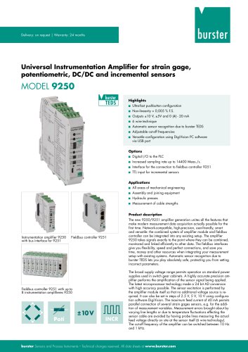 Data Sheet Model 9250
7 Pages
 Operation manual 2025
76 Pages
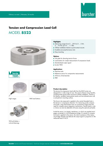 Data Sheet Model 8523 (2025)
8 Pages
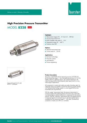 Data-Sheet- Model 8228
6 Pages
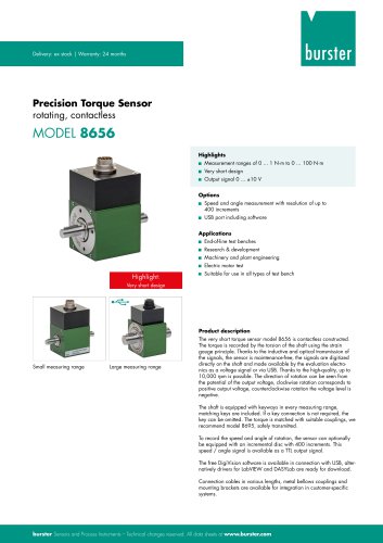 Data Sheet Model 8656
7 Pages
 Brochure Load Cell
25 Pages
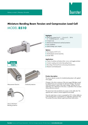 Data Sheet Model 8510 (2025)
5 Pages
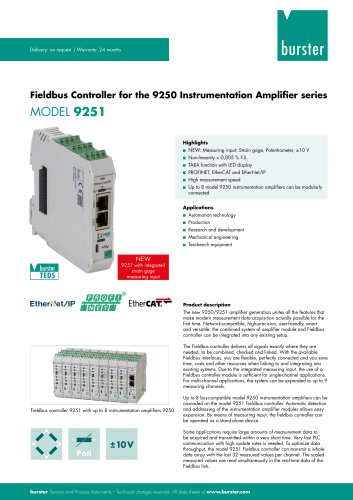 Data-Sheet - 9251
6 Pages
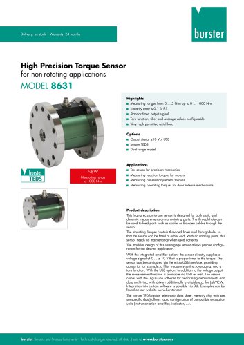 Data sheet Model 8631
5 Pages
 Data Sheet Model 2511
6 Pages
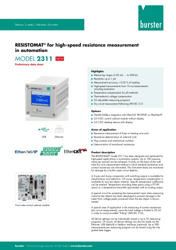 Data Sheet Model 2311
5 Pages
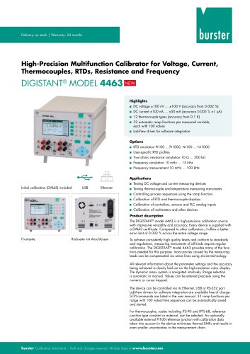 Data Sheet Model 4463
5 Pages
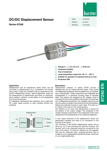 Data Sheet Typ 87240
2 Pages
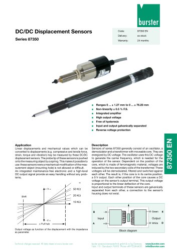 Data Sheet Series 87350
2 Pages
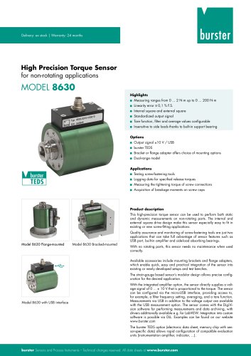 Data Sheet Model 8630
6 Pages
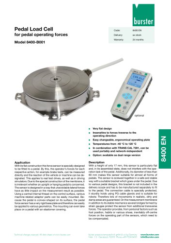 Data Sheet Model 8400-B001
2 Pages
 Load-cell
25 Pages
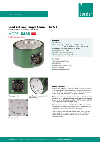 Data Sheet Model 8565
5 Pages
 Torque Sensors
9 Pages
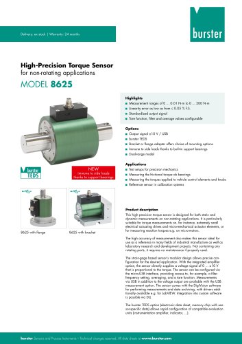 Data Sheet Typ 8625
7 Pages
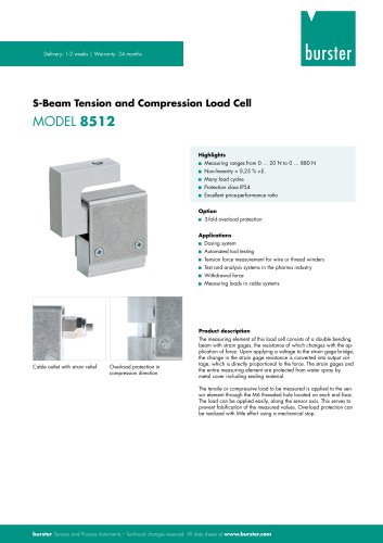 Data Sheet Typ 8512 (2025)
5 Pages
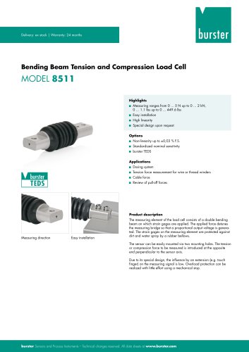 Data Sheet Model 8511 (2025)
6 Pages
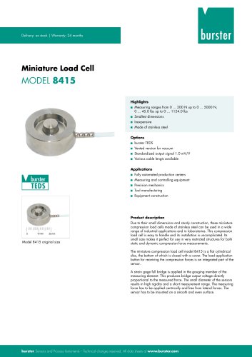 Data Sheet Model 8415 (2025)
6 Pages
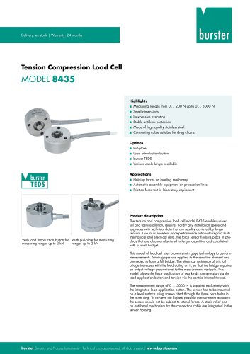 Data sheet Model 8435 (2025)
7 Pages
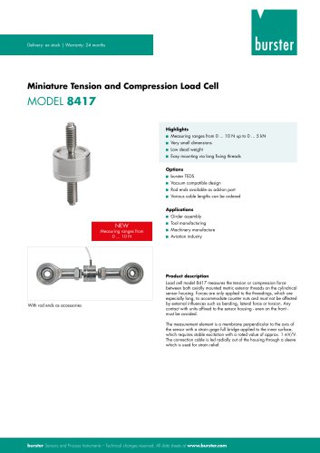 Data Sheet Typ 8417 (2025)
7 Pages
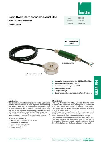 Data Sheet Typ 8532 (2025)
2 Pages
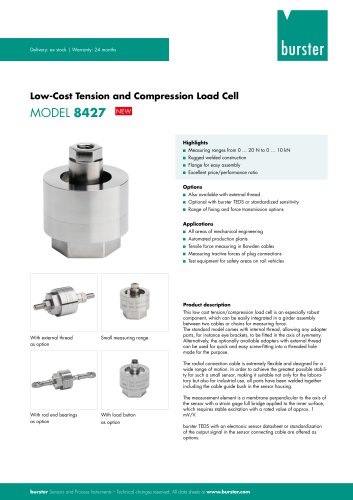 Data Sheet 8427 (2025)
7 Pages
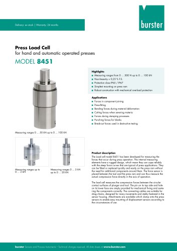 Data Sheet Motel 8451 (2025)
7 Pages
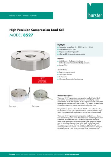 Data Sheet Model 8527 (2025)
7 Pages
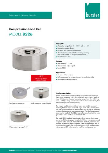 Data Sheet Model 8526 (2025)
9 Pages
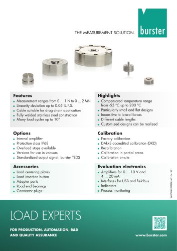 Flyer Load Experts 2025
1 Page
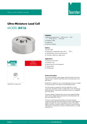 Data sheet Typ 8416 (2025)
6 Pages
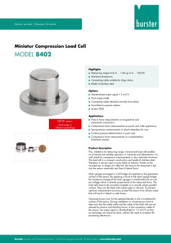 Data Sheet Model 8402 (2025)
6 Pages
 2511 BATTERY MEASURING MODULE
14 Pages
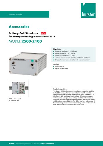 Data Sheet- Model 2500-Z100
2 Pages
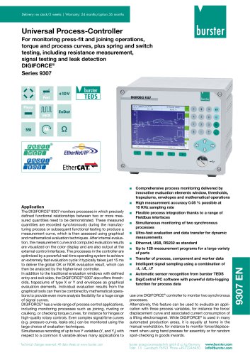 Data Sheet Typ 9307
6 Pages
 Data Sheet Model 9210
5 Pages
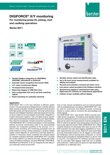 Data Sheet Typ 9311
6 Pages
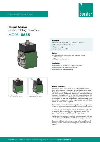 Data Sheet Typ 8655 (2025)
7 Pages
 Displacement Sensors 2025
2 Pages
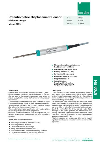 Data sheet Model 8709 (2025)
2 Pages
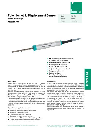 Data sheet Model 8709
2 Pages
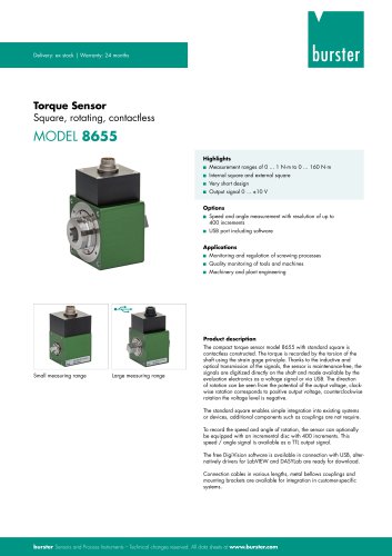 Data Sheet Typ 8655
7 Pages
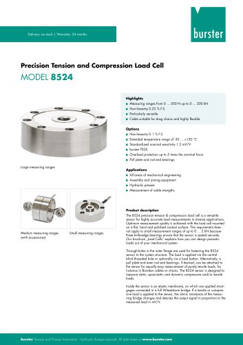 Data Sheet Model 8524
8 Pages
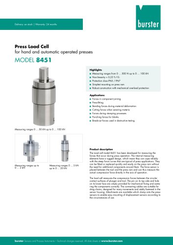 Data Sheet Motel 8451
7 Pages
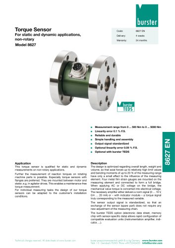 Data Sheet Typ 8627
2 Pages
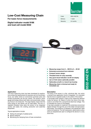 Data Sheet Model 9186/8532
2 Pages
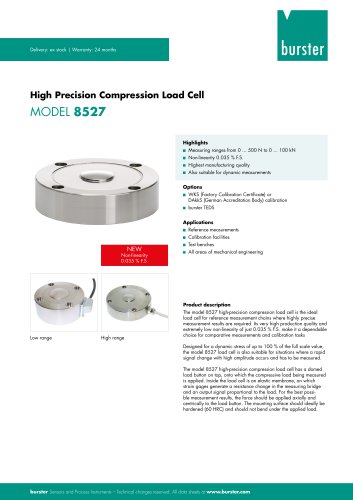 Data Sheet Model 8527
7 Pages
 Data Sheet Typ 8512
5 Pages
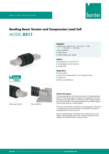 Data Sheet Model 8511
6 Pages
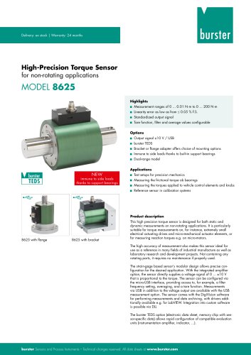 Data Sheet Typ 8625
7 Pages
 Data Sheet Typ 8532
2 Pages
 Data Sheet Model 8561
6 Pages
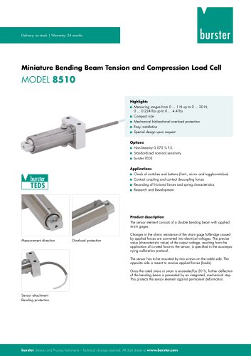 Data Sheet Model 8510
5 Pages
 Data Sheet Model 8523
8 Pages
 Data Sheet Model 8526
9 Pages
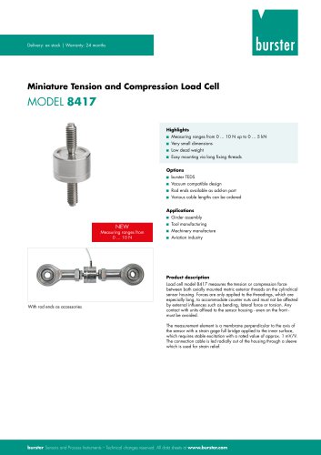 Data Sheet Typ 8417
7 Pages
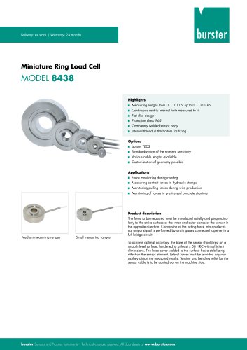 Data Sheet - Model 8438
6 Pages
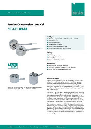 Data sheet Model 8435
7 Pages
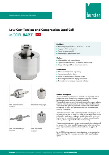 Data Sheet 8427
7 Pages
 Data Sheet Model 8402
6 Pages
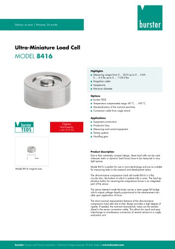 Data sheet Typ 8416
6 Pages
 Press fitting - the reliable way
11 Pages
 Data Sheet Model 9243
2 Pages
 Displacement Sensors
2 Pages
 Flyer Load Experts
1 Page
 Sensor Solutions
1 Page
 Data Sheet Model 9235
2 Pages
 Data sheet Series 8738
2 Pages
 Flyer Battery Tester
1 Page
 Data Sheet Model 2560
5 Pages
 Operation manual
76 Pages
 Data Sheet Typ 8739
2 Pages
 RESISTOMAT® Model 2329
4 Pages
 Data Sheet Model 2550
4 Pages
 Data Sheet Typ 8645
5 Pages
 Flyer Displacement Sensor
2 Pages
 Data Sheet - Model 8670
4 Pages

























Archived catalogs
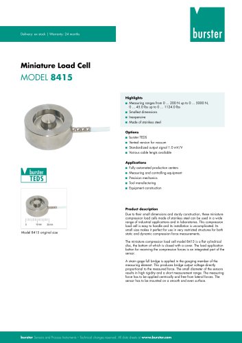 Data Sheet Model 8415
6 Pages
- Display module
- Pressure transmitter
- BURSTER tension/compression load cell
- BURSTER steel load cell
- Calibration system
- Analog pressure transmitter
- BURSTER strain gauge load cell
- Digital indicator
- BURSTER stainless steel load cell
- Waterproof pressure transmitter
- Membrane pressure transmitter
- Stainless steel pressure transmitter
- Panel panel meter
- Relative pressure transmitter
- Position transducer
- Beam type force sensor
- Signal amplifying integrated circuit
- BURSTER compression load cell
- Automated software