
- Catalogs
- burster Measurement Solutions GmbH
- Operation Manual Digital Indicator Model 9163

Operation Manual Digital Indicator Model 9163
Operation Manual Digital Indicator Model 9163
The Model 9163 Digital Indicator is designed for measuring rapidly changing electrical quantities, supporting up to two analog main inputs and two auxiliary inputs. It is suitable for applications like differential measurements and accommodates standard linear signals, pressure transducers, load cells, potentiometers, and thermocouples.
Users must adhere to safety warnings to prevent electric shock and injuries. Key precautions include not exceeding specified voltage ranges, disconnecting power before opening the device, and ensuring correct parameter settings. The device should not be used if damaged or in explosive areas.
The device can be installed as a panel-mount or bench-top unit. Installation instructions and dimensions are provided for proper setup. Electrical connections vary between single-channel and two-channel units, with detailed input and output configurations.
The manual outlines the basic operation, including accessing menus, adjusting parameters, and navigating the operating hierarchy. It also covers power-up procedures, self-diagnosis, and error handling during measurement mode.
Users can configure main and auxiliary inputs, select sensor excitation, and specify output parameters. The device supports analog output adjustments and setting alarm limits, with options for enabling and configuring alarms.
Configuration of serial and Profibus interfaces is detailed for instruments with these options. Hardware settings include accessing protected areas, parameter locks, and instrument settings like mathematical functions and display configurations.
The manual provides guidance on sensor-specific calibration for various signal types, including potentiometers, strain gauges, RTDs, and thermocouples. Maintenance instructions cover cleaning, repair, and troubleshooting.
Technical specifications are provided, along with order codes, accessories, and options available for the Model 9163 Digital Indicator.
The Model 9163 supports various input types including linear DC current and voltage signals, potentiometers, PT100 sensors, and strain gauge sensors. It offers multiple output options such as relay outputs and analog outputs with configurations for voltage and current.
The document emphasizes the risk of electric shock and the necessity for Class II insulation for external control circuits. It also specifies the use of VDE standard capacitors and appropriate grounding techniques to ensure safety.
Instructions are provided for arranging input leads separately from power supply lines, using twisted/screened cables, and connecting RC elements or diodes for load suppression. Specific pin assignments for various inputs and outputs are detailed, along with adapter cable configurations.
The indicator can operate on a standard power supply of 100 to 240 V AC/DC or an optional 20 to 27 V AC. It requires a circuit breaker with a fuse and appropriate cables for electrical connections.
The front panel includes a process value display, sub-display, cursor buttons, and status indicators for alarms and functions. The interface allows for parameter adjustments and configuration of alarm limits and calibration settings.
The document includes information on digital inputs and outputs, serial interfaces (RS232 and RS485), and the use of line filters and voltage stabilizers to manage interference and voltage fluctuations.
The calibration process involves connecting sensors to the digital indicator and navigating through specific menu options to set parameters for calibration at 0 mV and 50 mV. The ambient temperature must be entered to complete the thermocouple calibration. The document emphasizes the importance of connecting all sensors to avoid measurement errors.
Linearization is performed through the menu, allowing selection from various linearization types. The process involves setting the number of intervals and scale values, with specific instructions for types 0 to 4 and type 5. The document provides equations for calculating interval values.
Instructions are provided for resetting the calibration to factory settings by adding specific codes to the input whose calibration needs resetting.
The digital indicator can be powered up or down via software, with instructions for enabling or disabling the ON/OFF function. The document details the procedure for switching the device to stand-by mode and back to operational mode.
Maintenance involves cleaning the front panel and internal components, with warnings against using hydrocarbon-based solvents. Repairs should only be conducted by authorized personnel to maintain warranty validity. Troubleshooting guidance is provided for common issues, such as power supply problems and display errors.
The document lists detailed technical specifications, including display characteristics, accuracy, input types, sampling intervals, and power supply requirements. It also covers sensor excitation, serial interface options, and environmental operating conditions.
The document concludes with a list of adapter cables and software options available for the Model 9163 Digital Indicator, including configuration and analysis software.
The appendix provides detailed menu options for the Model 9163 Digital Indicator, including configuration settings, input parameters, and output specifications. It includes tables that outline default values, configuration modes, and descriptions for various settings.
- Level 1 Menu: Displays settings for primary and auxiliary inputs, mathematical function results, and limit settings.
- Information Menu: Contains software version, equipment code, and error codes for inputs and functions.
- Input Menus (INP.1 to INP.4): Define sensor types, digital filters, decimal point positions, scale values, offsets, and sensitivities for each input.
- Limit Menu (ALL): Specifies references, types, hysteresis, activation times, and character strings for limits.
- Output Menu (OVT): Details references for outputs, analog output types, scale values, and sensor-excitation selections.
- Password Menu (PAS): Includes password and protection code settings.
- Extended Menu (XRD): Covers mathematical functions, operand settings, coefficients, and digital input functions.
- Linearization Menu (LIN): Describes linearization types, intervals, and values assigned to scale points.
The document includes block diagrams illustrating the functional layout and operation of the Model 9163 Digital Indicator.
Catalog excerpts
OPERATION MANUAL prazisionsmesstechnik gmbh & co kg All rights reserved burster praezisionsmesstechnik gmbh & co kg Talstrasse 1 - 5 P.O. Box 1432 Germany Germany E-Mail: [email protected]
Open the catalog to page 1
Digital indicator Exclusion of warranty liability for operating manuals All information in the present documentation was prepared and compiled with great care and reproduced subject to effective control measures. No warranty is provided for freedom from errors. We reserve the right to make technical changes. The present information as well as the corresponding technical data can change without notice. Reproduction of any part of this documentation or its processing or revision using electronic systems is prohibited without the manufacturer's prior written approval. Components, devices and measured...
Open the catalog to page 2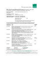
EU-Konformitatserklarung (nach en iso/i ec i 7050-1:2010) Name des Aussteliers: Issuer’s name: burster prazisionsmesstechnik gmbh & co kg Anschrift des Aussteliers: Issuer’s address: Digitalanzeiger / SENSORMASTER Digital Indicator / SENSORMASTER Model number/type: Diese Erklarung beinhaltet obengenannte Produkte mit alien Optionen This declaration covers all options of the above product(s) Das oben beschriebene Produkt ist konform mit den Anforderungen derfolgenden Dokumente: The object of the declaration described above is in conformity with the requirements of the following documents' Dokument-Nr....
Open the catalog to page 3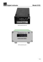
Digital indicator
Open the catalog to page 5
Digital indicator
Open the catalog to page 6
Digital indicator
Open the catalog to page 7
Digital indicator
Open the catalog to page 10
Digital indicator 1. For your safety 1.1 Warnings and notes The symbol on the instrument denotes that the user should refer to the operating instructions DANGER! in this manual warns of immediate hazards which result in severe personal injury or death. WARNING! in this manual refers to a hazard or unsafe practice which can result in severe personal injury or death. CAUTION! in this manual refers to a hazard or unsafe practice which can result in personal injury or product or property damage. Note: This indicates precautions which should be observed to ensure proper handling of the equipment
Open the catalog to page 11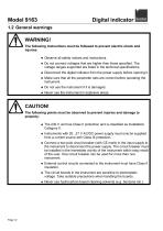
Digital indicator WARNING! The following instructions must be followed to prevent electric shock and injuries: * Observe all safety notices and instructions. * Do not connect voltages that are higher than those specified. The voltage ranges supported are listed in the technical specifications. * Disconnect the digital indicator from the power supply before opening it. * Make sure that all the parameter sets are correct before operating the instrument. * Never use the instrument in explosive areas. CAUTION! The following points must be observed to prevent injuries and damage to property: * The...
Open the catalog to page 12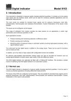
Digital indicator 2. Introduction This instrument is designed to measure rapidly changing electrical quantities. It includes up to two analog main inputs plus two auxiliary inputs, which can be used for numerous potential applications such as differential measurements. The main inputs are suitable for standard linear signals and for pressure transducers, load cells, potentiometers, thermocouples and resistance thermometers. Custom linearization of the inputs is also possible. The inputs can be configured via the keypad. This range of indicators from burster provides the ideal solution for all...
Open the catalog to page 13
Digital indicator 2.2.1 Customer service department For enquiries about repairs Please have your serial number ready for such enquiries. We need this number to find out the technical specifications of your instrument and hence provide you with rapid assistance. The serial number is shown on the type plate. burster praezisionsmesstechnik gmbh & co kg provides a manufacturer's warranty for a period of 24 months after delivery. Any repairs required during this time will be made without charge. Damage caused by improper use of the device is not covered by the warranty. If you are returning the device...
Open the catalog to page 14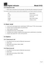
Digital indicator Model 9163 2.2.4 Equipment data > Please enter the information from the type plate in the table below after unpacking the instrument. If you need to contact the burster Customer Service department, you will need to quote this information. (serial number) (finished product code) (order code) (type of power supply) (software version) • 1 main input for strain gauge sensors, potentiometers, DC/DC sensor, PT100 or thermocouples. • 2 auxiliary inputs for standard signals and potentiometers • 1 power supply for transmitters • 2 configurable data inputs, p switching (PNP) • 1 selectable...
Open the catalog to page 15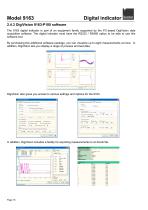
Digital indicator 2.4.3 DigiVision 9163-P100 software The 9163 digital indicator is part of an equipment family supported by the PC-based DigiVision data acquisition software. The digital indicator must have the RS232 / RS485 option to be able to use this software tool. By purchasing this additional software package, you can visualize up to eight measurements at once. In addition, DigiVision lets you display a range of process and test data. DigiVision also gives you access to various settings and options for the 9163. In addition, DigiVision includes a facility for exporting measurements to...
Open the catalog to page 16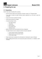
Digital indicator Model 9163 3. Preparing for use 3.1 Unpacking Perform these tasks immediately after unpacking: > Enter the technical data from the type plate in the table in section 2.2.4: "Equipment data". If you need to contact the burster Customer Service department, you will need to quote this information. > Inspect the instrument carefully for damage. > Check that the shipment is complete. A standard package includes: o 9163 digital indicator o 2 fixing clips o Shock protection o Dust protection seal o Operating manual > Make sure that the order code matches the device configuration. The...
Open the catalog to page 17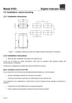
Digital indicator 3.2 Installation / panel-mounting 3.2.1 Installation dimensions Figure 1: Installation dimensions of the 9163 digital indicator (dimensions in millimeter) Read the basic installation rules before you install the unit. If you do not follow our safety instructions, there may be problems with electrical safety and electromagnetic compatibility. Furthermore, disregarding the safety instructions will forfeit the warranty. Basic installation rules for the 9163 If you connect the unit to devices that are not electrically isolated (e.g. thermocouples): Provide a dedicated conductor...
Open the catalog to page 18All Burster Measurement Solutions GmbH catalogs and technical brochures
 Operation Manual Model 8565
24 Pages
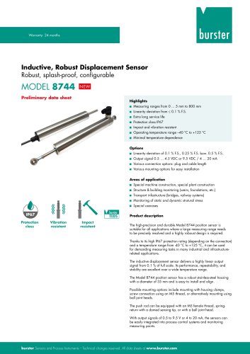 Data Sheet Model 8744
6 Pages
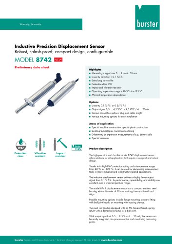 Data Sheet Model 8742
6 Pages
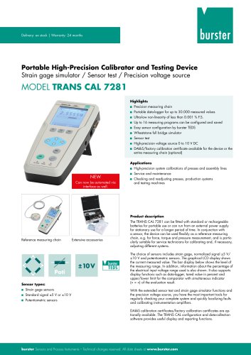 Data Sheet Model 7281
5 Pages
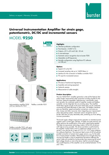 Data Sheet Model 9250
7 Pages
 Operation manual 2025
76 Pages
 Data Sheet Model 8523 (2025)
8 Pages
 Data-Sheet- Model 8228
6 Pages
 Data Sheet Model 8656
7 Pages
 Brochure Load Cell
25 Pages
 Data Sheet Model 8510 (2025)
5 Pages
 Data-Sheet - 9251
6 Pages
 Data sheet Model 8631
5 Pages
 Data Sheet Model 2511
6 Pages
 Data Sheet Model 2311
5 Pages
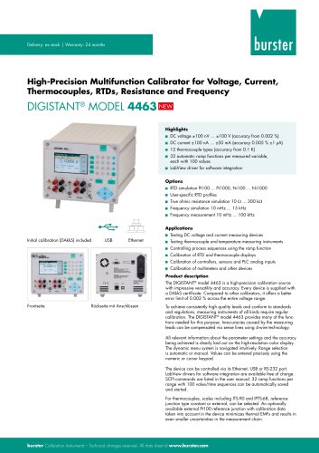 Data Sheet Model 4463
5 Pages
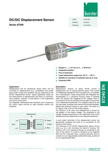 Data Sheet Typ 87240
2 Pages
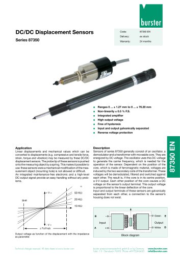 Data Sheet Series 87350
2 Pages
 Data Sheet Model 8630
6 Pages
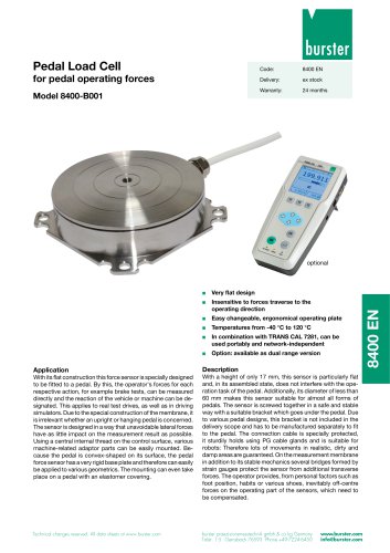 Data Sheet Model 8400-B001
2 Pages
 Load-cell
25 Pages
 Data Sheet Model 8565
5 Pages
 Torque Sensors
9 Pages
 Data Sheet Typ 8625
7 Pages
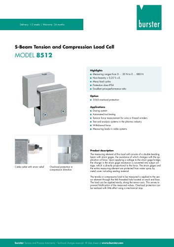 Data Sheet Typ 8512 (2025)
5 Pages
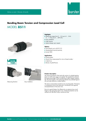 Data Sheet Model 8511 (2025)
6 Pages
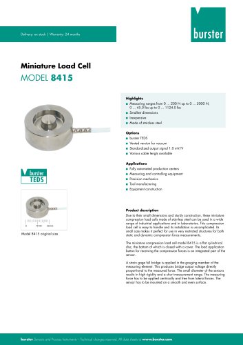 Data Sheet Model 8415 (2025)
6 Pages
 Data sheet Model 8435 (2025)
7 Pages
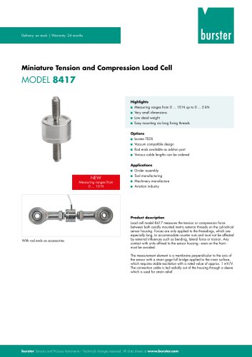 Data Sheet Typ 8417 (2025)
7 Pages
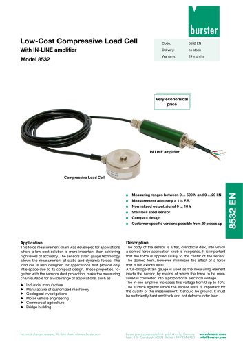 Data Sheet Typ 8532 (2025)
2 Pages
 Data Sheet 8427 (2025)
7 Pages
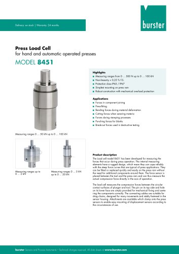 Data Sheet Motel 8451 (2025)
7 Pages
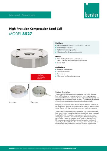 Data Sheet Model 8527 (2025)
7 Pages
 Data Sheet Model 8526 (2025)
9 Pages
 Flyer Load Experts 2025
1 Page
 Data sheet Typ 8416 (2025)
6 Pages
 Data Sheet Model 8402 (2025)
6 Pages
 2511 BATTERY MEASURING MODULE
14 Pages
 Data Sheet- Model 2500-Z100
2 Pages
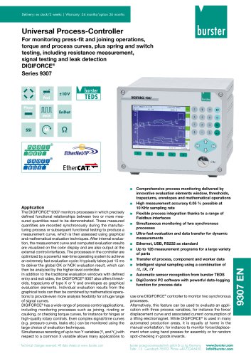 Data Sheet Typ 9307
6 Pages
 Data Sheet Model 9210
5 Pages
 Data Sheet Typ 9311
6 Pages
 Data Sheet Typ 8655 (2025)
7 Pages
 Displacement Sensors 2025
2 Pages
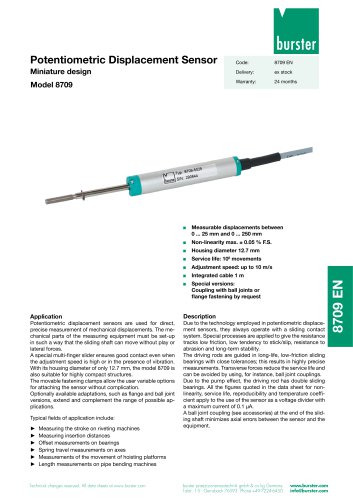 Data sheet Model 8709 (2025)
2 Pages
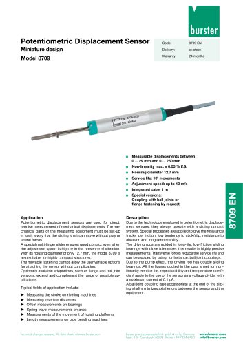 Data sheet Model 8709
2 Pages
 Data Sheet Typ 8655
7 Pages
 Data Sheet Model 8524
8 Pages
 Data Sheet Motel 8451
7 Pages
 Data Sheet Typ 8627
2 Pages
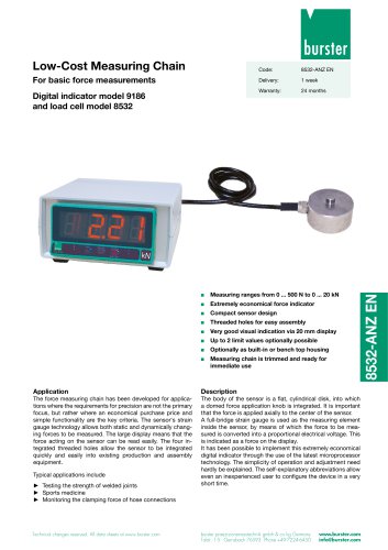 Data Sheet Model 9186/8532
2 Pages
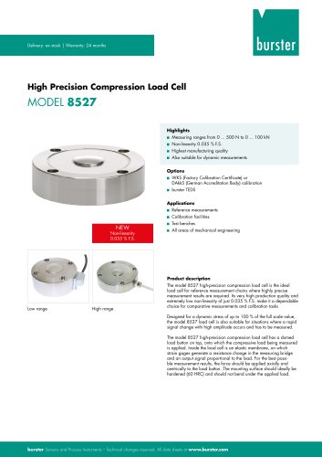 Data Sheet Model 8527
7 Pages
 Data Sheet Typ 8512
5 Pages
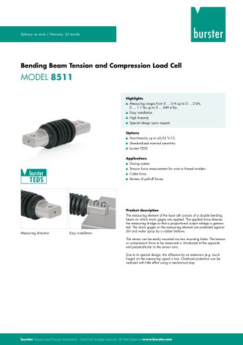 Data Sheet Model 8511
6 Pages
 Data Sheet Typ 8625
7 Pages
 Data Sheet Typ 8532
2 Pages
 Data Sheet Model 8561
6 Pages
 Data Sheet Model 8510
5 Pages
 Data Sheet Model 8523
8 Pages
 Data Sheet Model 8526
9 Pages
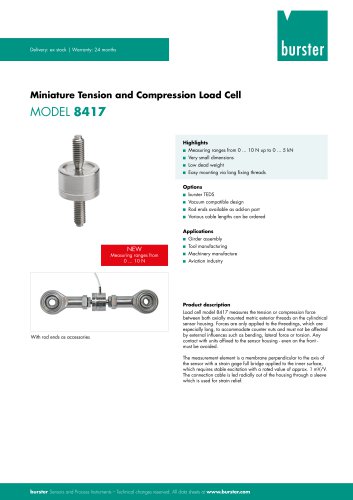 Data Sheet Typ 8417
7 Pages
 Data Sheet - Model 8438
6 Pages
 Data sheet Model 8435
7 Pages
 Data Sheet 8427
7 Pages
 Data Sheet Model 8402
6 Pages
 Data sheet Typ 8416
6 Pages
 Press fitting - the reliable way
11 Pages
 Data Sheet Model 9243
2 Pages
 Displacement Sensors
2 Pages
 Flyer Load Experts
1 Page
 Sensor Solutions
1 Page
 Data Sheet Model 9235
2 Pages
 Data sheet Series 8738
2 Pages
 Flyer Battery Tester
1 Page
 Data Sheet Model 2560
5 Pages
 Operation manual
76 Pages
 Data Sheet Typ 8739
2 Pages
 RESISTOMAT® Model 2329
4 Pages
 Data Sheet Model 2550
4 Pages
 Data Sheet Typ 8645
5 Pages
 Flyer Displacement Sensor
2 Pages
 Data Sheet - Model 8670
4 Pages


































Archived catalogs
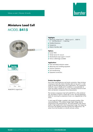 Data Sheet Model 8415
6 Pages

- Pressure transmitter
- BURSTER tension/compression load cell
- BURSTER steel load cell
- Calibration system
- Analog pressure transmitter
- BURSTER strain gauge load cell
- BURSTER stainless steel load cell
- Waterproof pressure transmitter
- Membrane pressure transmitter
- Stainless steel pressure transmitter
- Panel panel meter
- Relative pressure transmitter
- Position transducer
- Beam type force sensor
- Signal amplifying integrated circuit
- BURSTER compression load cell
- Automated software