
- Catalogs
- burster Measurement Solutions GmbH
- Operation manual 2025

Operation manual 2025
Operation manual 2025
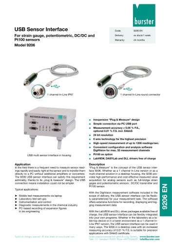
The USB Sensor Interface Model 9206 is a versatile device for acquiring and processing sensor signals, suitable for measuring mechanical variables like force, torque, and pressure. It features a high-performance A/D converter and supports data acquisition up to 1200 readings/s, with a free software version supporting up to 200 readings/s.
Designed for industrial and laboratory settings, the interface is compatible with various analog sensors and is ideal for mobile test measurements and diagnostics in industries such as chemical and biotechnology.
Customers can contact burster praezisionsmesstechnik gmbh & co kg for repairs or technical queries. A 24-month warranty is provided from the date of delivery.
Users must adhere to safety procedures to prevent electric shock and injuries, ensuring the device is used outside explosive areas and remains undamaged. Repairs should be conducted by the manufacturer.
The manual includes detailed instructions for unpacking, installation, and sensor connection, covering various sensor types like Pt100 and strain gauge sensors.
Configured via USB, the device includes DigiVision software for configuration and analysis. The manual covers software installation, system requirements, and device settings, including sensor adjustment methods.
The interface supports device detection, operation, and measurement functionalities, including display, tare function, and measurement rate selection, with options for documentation and exporting reports.
Guidelines for maintenance, cleaning, and disposal are provided to ensure device longevity and proper functioning.
The manual concludes with technical specifications and available accessories for the USB Sensor Interface Model 9206.
The device is covered by a warranty for repairs, provided there is no damage from improper use. Liability for consequential damage is not accepted.
The manual provides essential information on the operation, installation, and configuration of the model 9206 USB Sensor Interface, emphasizing the importance of following instructions to avoid faults and risks.
The device is packaged to prevent shock damage during shipment. The package includes the USB Sensor Interface, a CD-ROM with software, and a manual.
The device can be fixed using hose clips or cable ties, with careful handling required when opening the tubular housing.
The device has an IP67 protection rating and operates within a temperature range of -20°C to +60°C.
The device features screw terminals for connections and supports various sensor types, with proper connection crucial to avoid damage.
LED indicators display different operational states, such as errors and standard operation.
The device requires a Windows operating system and specific hardware specifications, with software installation involving running a setup from the provided CD-ROM.
The device processes signals using a 24-bit A/D converter, with signal conditioning options like averaging to improve accuracy.
Powered via USB, with an option for an external power supply for high-current sensors.
The PC configuration program allows for convenient device configuration via USB, supporting tasks like creating and exporting device configurations and viewing measurements graphically.
The device finder automatically detects connected interfaces, allowing users to configure them and access settings like device names and calibration dates.
Measurement input ranges include 15 mV to +/-10V, with options to improve accuracy by averaging signal values.
Possible excitation voltages are 2.5 V and 5 V, as specified in the datasheet.
The interface can be calibrated using a two-point calibration procedure, defining the relationship between electrical signals and measurement display.
A 6-wire connection method is recommended for optimal accuracy, though a 4-wire method is often sufficient.
This involves a two-stage online teach-in process for sensor data, setting zero and upper scale values.
This method uses test certificates to directly enter sensor data into the interface.
A two-point calibration procedure is used, with connection details provided in the test certificate.
The document outlines the calibration process, focusing on setting measurement ranges using a calibrated gage block.
The maximum applicable excitation voltage is specified in the test certificate, with 5 V recommended for practical measurements.
Connector-pin numbering is provided in the test certificate, with adjustment involving a two-point calibration procedure.
Adjustment involves a two-stage online teach-in method for sensor data.
Describes the linearization of Pt100 sensors using standard coefficients, with calibration at multiple points.
Device detection is possible with the licensed software version, with the measurement screen displaying curves for each channel.
Two acquisition modes are available, with trigger settings for defining start and stop conditions.
The software provides options for saving raw data and exporting reports to Excel.
No user maintenance is required, and repairs must be conducted by the manufacturer.
Users must return used batteries as per the battery ordinance, with disposal through household waste prohibited.
- Input Signal: Full-bridge strain gage with excitation of 2.5 V or 5 V.
- Voltage Reference Signal: 0 V to ±10 V with input impedance >1 GΩ.
- General Data: Measuring error is less than 0.05% of full scale.
- Enclosure: IP67 protection, made of aluminium.
- Supply Voltage: Via USB port or power cable.
- Signal Processing: A/D conversion with 24 bits.
- Accessories: Configuration and analysis software, license code for multi-channel version, and adapter cables.
- Options: Calibration service for the complete measuring chain.
Catalog excerpts
OPERATION MANUALUSB Sensor Interface Model 9206 ©2024 burster praezisionsmesstechnik gmbh & co kg All rights reserved burster praezisionsmesstechnik gmbh & co kg TalstraGe 1 - 5 P.O.Box 1432 Germany Germany E-Mail [email protected] www.burster.com
Open the catalog to page 1
USB Sensor Interface Model 9206 Warranty - exclusion of liability All information in the present documentation was prepared and compiled with great care and reproduced subject to effective control measures. No warranty is provided for freedom from errors. We reserve the right to make technical changes. The present information as well as the corresponding technical data can change without notice. Reproduction of any part of this documentation or its processing or revision using electronic systems is prohibited without the manufacturer's prior written approval. Components, devices and measured...
Open the catalog to page 2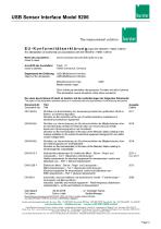
USB Sensor Interface Model 9206The measurement solution. EU-Konformitstserklarung (nach en iso/iec i 7050-1:2010) EU-Declaration of conformity (in accordance with EN ISO/IEC 17050-1:2010) Issuer’s name: burster prazisionsmesstechnik grnbh & co kg Anschrift des Ausstellers: Issuer’s address: USB-(Multi)Sensor-lnterface USB-(Multi) Sensor-Interface Modellnummer(n) (Typ): Model number/type:Diese Erklarung beinhaltet obengenannte Produkte mit alien Optionen This declaration covers all options of the above product(s) Das oben beschriebene Produkt ist konform mit den Anforderungen derfolgenden Dokumente:...
Open the catalog to page 3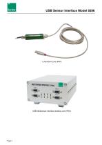
USB Sensor Interface Model 9206 USB Multisensor-Interface desktop unit (IP20)
Open the catalog to page 4
USB Sensor Interface Model 9206 Warning! The following instructions must be followed to prevent electric shock and injuries: Follow all equipment safety procedures. Only use the device outside from explosive areas. Only use the device when it is undamaged. Do not apply more than the rated voltage. See specifications for supported ranges. Any repairs that may be needed must be performed only at the manufacturer's premises. Caution! The following points must be followed to prevent injuries and damage to property: Do not use any cleaning agents that contain organic solvents or concentrated...
Open the catalog to page 5
USB Sensor Interface Model 9206
Open the catalog to page 6
7.4 Adjustment of a transmitter having a voltage output using the teach-in method ... 56
Open the catalog to page 7
USB Sensor Interface Model 9206 1. The model 9206 USB Sensor Interface is intended for the acquisition and processing of sensor signals. The model 9206 USB Sensor Interface is a user-configurable single-channel device, or optionally a multi-channel device housed in a desktop unit. The device is configured via the USB port. The model 9206 USB Sensor Interface is ideally suited to measuring mechanical variables such as force, torque, pressure, acceleration, displacement and angle. It makes acquisition and processing of straingage, potentiometric and standard signals straightforward. Signal conditioning...
Open the catalog to page 9
USB Sensor Interface Model 92061.1 Normal use The model 9206 USB Sensor Interface has been developed specifically for high-speed measurements, and therefore covers a huge range of applications. Designed for use with a variety of analog sensors, the device can capture a huge range of output signals for conditioning in mobile systems. Industry-compatible connection and installation technologies make it easier for the user to adapt and integrate the unit in existing mechanical and electrical environments. The outstanding measuring quality combined with a large number of values used for averaging...
Open the catalog to page 10
USB Sensor Interface Model 9206 1.2.3 Factory warranty burster praezisionsmesstechnik gmbh & co kg provides a manufacturer's warranty for a period of 24 months after delivery. Any repairs required during this time will be made without charge. Damage caused by improper use of the device is not covered by the warranty. If the device needs to be returned for repairs, please note the following requirements for packing and shipping: • If you have a problem with the device, please attach a note to the case summarizing the fault. The technical data can change at any time without notification. We also...
Open the catalog to page 11
USB Sensor Interface Model 92062. Preparation2.1 Unpacking The unit is packaged for protection against shock during shipment. > Carefully unpack the unit and verify that all items are present. > Inspect the instrument carefully for damage. If you suspect that the unit has been damaged during shipping, notify the delivery company immediately. The packaging should be retained for examination by a representative of the manufacturer and/or the delivery company. The model 9206 USB Sensor Interface must be shipped only in its original packaging provided by us or in a container capable of providing...
Open the catalog to page 12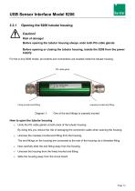
USB Sensor Interface Model 9206 2.3.1 Opening the 9206 tubular housing Caution! Risk of damage! Before opening the tubular housing always undo both PG cable glands. Before opening or closing the tubular housing, isolate the 9206 from the power supply. For the in-line 9206 model, all controls and connections are located inside the tubular housing. Finely knurled end-fitting coarsely knurled end-fitting One of the end fittings is coarsely knurled. How to open the tubular housing Undo the PG cable glands at both ends of the tubular housing. By doing this you reduce the risk of damaging the connection...
Open the catalog to page 13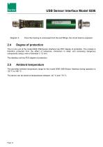
USB Sensor Interface Model 9206 Once the housing is unscrewed from the end fittings, the circuit board is exposed. The In Line unit of the model 9206 USB Sensor Interface has IP67 degree of protection. The module is therefore protected from the effect of temporary immersion in water and accessing dangerous components using a wire of diameter ≥ 1.0 mm. The desktop unit has IP20 degree of protection. Ambient temperature The permitted ambient temperature range for the model 9206 USB Sensor Interface during operation is -20 °C to +60 °C. The device can be stored at temperatures between -40 °C and...
Open the catalog to page 14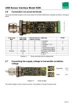
USB Sensor Interface Model 92062.6 Connection via screw-terminals The screw terminals located on the circuit board of the 9206 USB Sensor Interface are listed in the figure below. Diagram 3: Screw terminals and pin assignments Diagram 4: Solder bridges The solder bridges must be closed as shown. Only applies to tubular housing model.
Open the catalog to page 15All Burster Measurement Solutions GmbH catalogs and technical brochures
 Operation Manual Model 8565
24 Pages
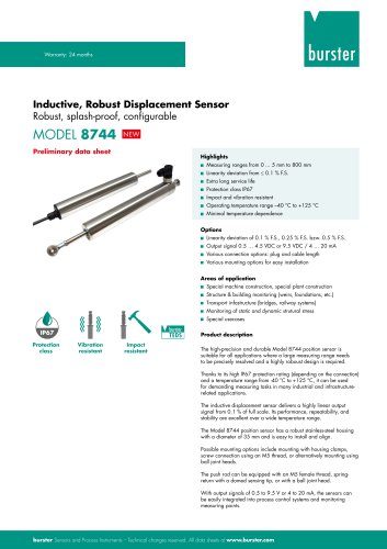 Data Sheet Model 8744
6 Pages
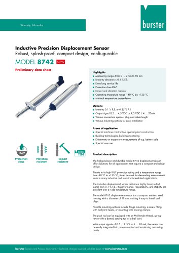 Data Sheet Model 8742
6 Pages
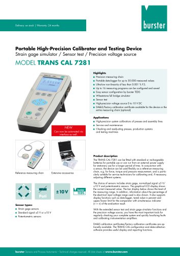 Data Sheet Model 7281
5 Pages
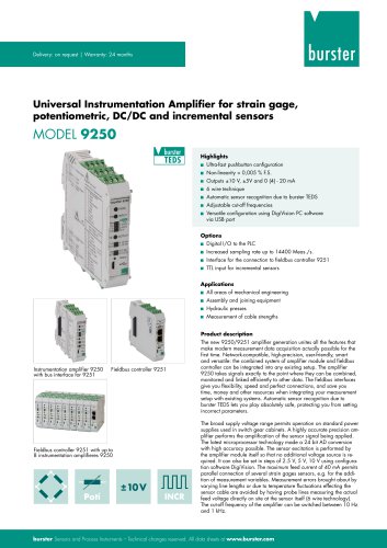 Data Sheet Model 9250
7 Pages
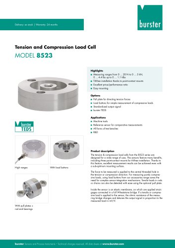 Data Sheet Model 8523 (2025)
8 Pages
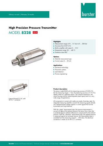 Data-Sheet- Model 8228
6 Pages
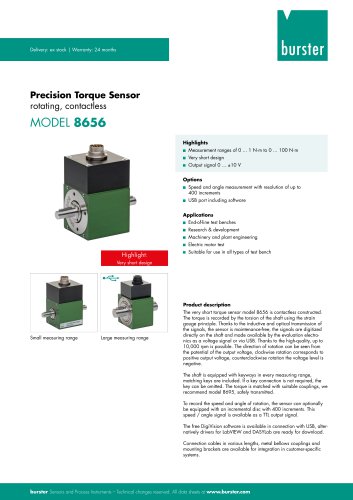 Data Sheet Model 8656
7 Pages
 Brochure Load Cell
25 Pages
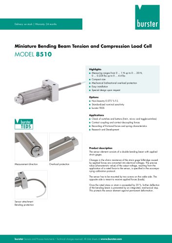 Data Sheet Model 8510 (2025)
5 Pages
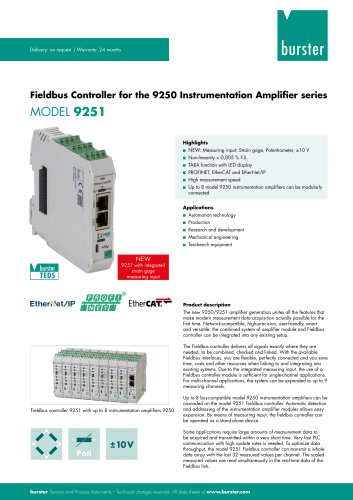 Data-Sheet - 9251
6 Pages
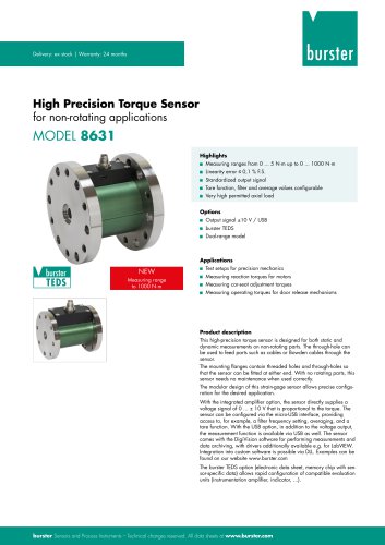 Data sheet Model 8631
5 Pages
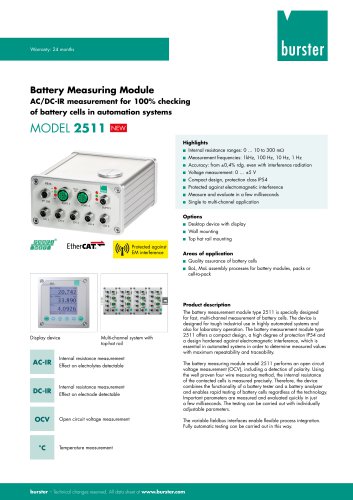 Data Sheet Model 2511
6 Pages
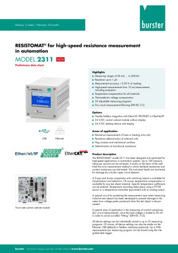 Data Sheet Model 2311
5 Pages
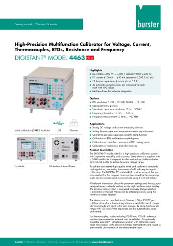 Data Sheet Model 4463
5 Pages
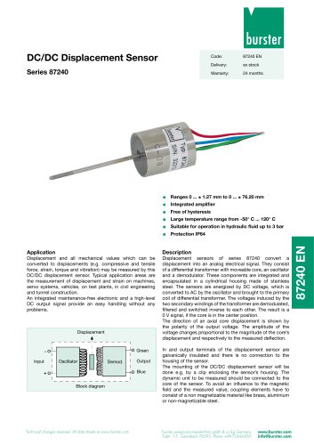 Data Sheet Typ 87240
2 Pages
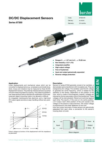 Data Sheet Series 87350
2 Pages
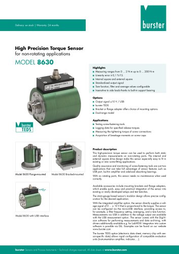 Data Sheet Model 8630
6 Pages
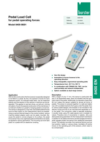 Data Sheet Model 8400-B001
2 Pages
 Load-cell
25 Pages
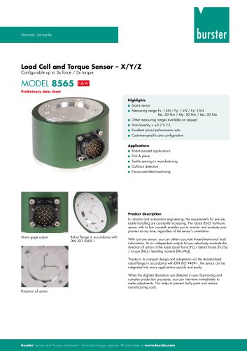 Data Sheet Model 8565
5 Pages
 Torque Sensors
9 Pages
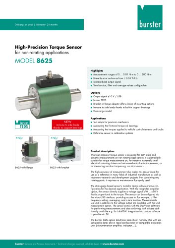 Data Sheet Typ 8625
7 Pages
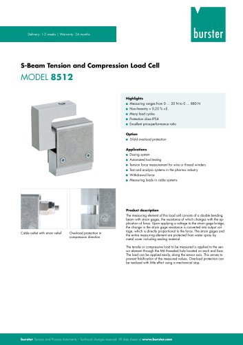 Data Sheet Typ 8512 (2025)
5 Pages
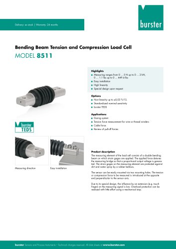 Data Sheet Model 8511 (2025)
6 Pages
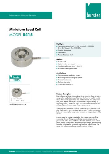 Data Sheet Model 8415 (2025)
6 Pages
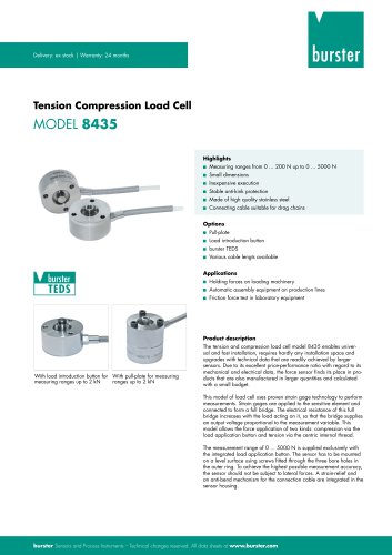 Data sheet Model 8435 (2025)
7 Pages
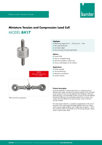 Data Sheet Typ 8417 (2025)
7 Pages
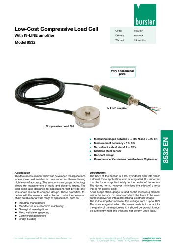 Data Sheet Typ 8532 (2025)
2 Pages
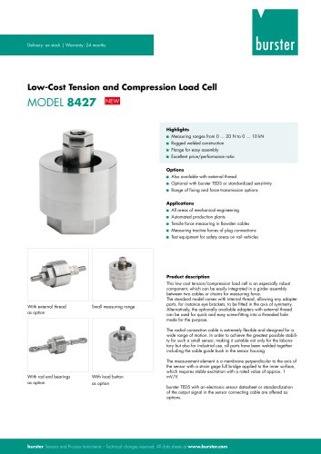 Data Sheet 8427 (2025)
7 Pages
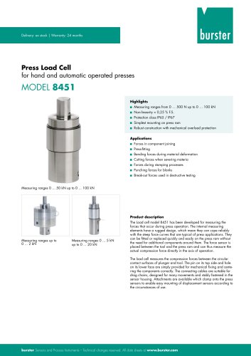 Data Sheet Motel 8451 (2025)
7 Pages
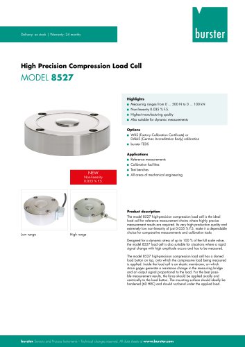 Data Sheet Model 8527 (2025)
7 Pages
 Data Sheet Model 8526 (2025)
9 Pages
 Flyer Load Experts 2025
1 Page
 Data sheet Typ 8416 (2025)
6 Pages
 Data Sheet Model 8402 (2025)
6 Pages
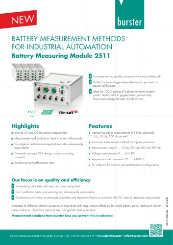
 2511 BATTERY MEASURING MODULE
14 Pages
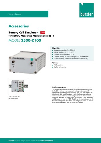 Data Sheet- Model 2500-Z100
2 Pages
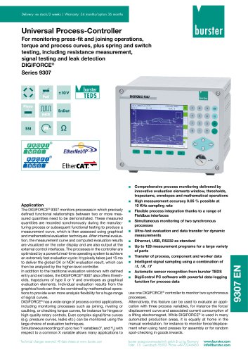 Data Sheet Typ 9307
6 Pages
 Data Sheet Model 9210
5 Pages
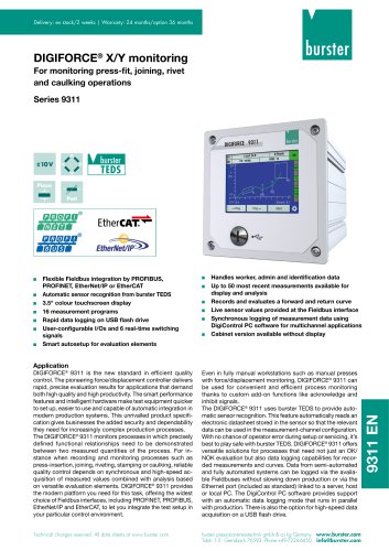 Data Sheet Typ 9311
6 Pages
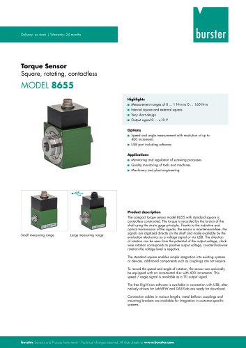 Data Sheet Typ 8655 (2025)
7 Pages
 Displacement Sensors 2025
2 Pages
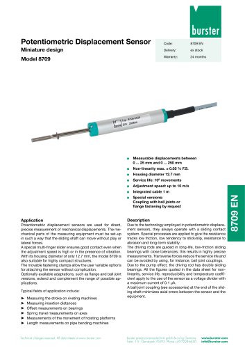 Data sheet Model 8709 (2025)
2 Pages
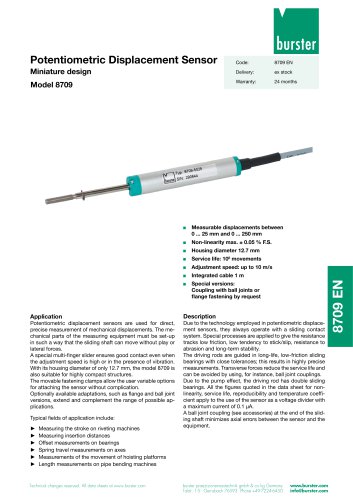 Data sheet Model 8709
2 Pages
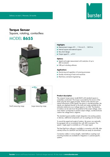 Data Sheet Typ 8655
7 Pages
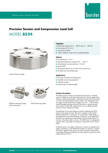 Data Sheet Model 8524
8 Pages
 Data Sheet Motel 8451
7 Pages
 Data Sheet Typ 8627
2 Pages
 Data Sheet Model 9186/8532
2 Pages
 Data Sheet Model 8527
7 Pages
 Data Sheet Typ 8512
5 Pages
 Data Sheet Model 8511
6 Pages
 Data Sheet Typ 8625
7 Pages
 Data Sheet Typ 8532
2 Pages
 Data Sheet Model 8561
6 Pages
 Data Sheet Model 8510
5 Pages
 Data Sheet Model 8523
8 Pages
 Data Sheet Model 8526
9 Pages
 Data Sheet Typ 8417
7 Pages
 Data Sheet - Model 8438
6 Pages
 Data sheet Model 8435
7 Pages
 Data Sheet 8427
7 Pages
 Data Sheet Model 8402
6 Pages
 Data sheet Typ 8416
6 Pages
 Press fitting - the reliable way
11 Pages
 Data Sheet Model 9243
2 Pages
 Displacement Sensors
2 Pages
 Flyer Load Experts
1 Page
 Sensor Solutions
1 Page
 Data Sheet Model 9235
2 Pages
 Data sheet Series 8738
2 Pages
 Flyer Battery Tester
1 Page
 Data Sheet Model 2560
5 Pages
 Operation manual
76 Pages
 Data Sheet Typ 8739
2 Pages
 RESISTOMAT® Model 2329
4 Pages
 Data Sheet Model 2550
4 Pages
 Data Sheet Typ 8645
5 Pages
 Flyer Displacement Sensor
2 Pages
 Data Sheet - Model 8670
4 Pages






















Archived catalogs
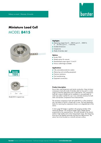 Data Sheet Model 8415
6 Pages
- BURSTER load cell
- Pressure transmitter
- BURSTER tension/compression load cell
- BURSTER steel load cell
- Calibration system
- Analog pressure transmitter
- BURSTER strain gauge load cell
- Digital indicator
- BURSTER stainless steel load cell
- Waterproof pressure transmitter
- Membrane pressure transmitter
- Stainless steel pressure transmitter
- Panel panel meter
- Relative pressure transmitter
- Position transducer
- Beam type force sensor
- Signal amplifying integrated circuit
- BURSTER compression load cell
- Automated software