
- Catalogs
- burster Measurement Solutions GmbH
- Operating Manual DIGIFORCE® model 9307

Operating Manual DIGIFORCE® model 9307
Operating Manual DIGIFORCE® model 9307
Catalog excerpts

OPERATING MANUALDIGIFORCE® model 9307 © 2018 burster praezisionsmesstechnik gmbh & co kg All rights reserved burster praezisionsmesstechnik gmbh & co kg Germany Germany Email: [email protected]
Open the catalog to page 1
Warranty disclaimer All information in the present documentation was prepared and compiled with great care and reproduced in accordance with effective control measures. This documentation may contain errors, and the information it contains and the corresponding technical data are subject to change without notice. Reproduction of any part of this documentation or its processing or revision using electronic systems is prohibited without the manufacturer's prior written approval. Components, devices and measurement sensors made by burster praezisionsmesstechnik (hereinafter referred to as the "product")...
Open the catalog to page 2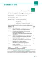
The measurement solution. EU-Konformitatserklarung (nach en iso/iec 17050-1:2010) EU-Declaration of conformity (in accordance with EN ISO/IEC 17050-1:2010) Issuer's name: burster prazisionsmesstechnik gmbh & co kg Anschrift des Ausstellers: Issuer’s address: Gegenstand der Erklarung: Object of the declaration: Universeller Prozess-Cortroller DIGIFORCE® Universal Process-Controller DIGIFORCE® Modellnummer(n) (Typ): Model number /type: Diese Erklarung beinhaltet obengenannte Produkte mit alien Optioner This declaration covers all options of the above product(s) Das oben beschriebene Produkt ist...
Open the catalog to page 3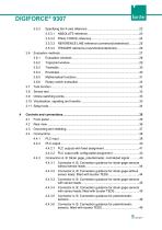
4.4.3.1 Connector A, B: Connection guidance for strain gage sensors 4.4.3.2 Connector A, B: Connection guidance for strain gage without 4.4.3.3 Connector A, B: Connection guidance for strain gage sensors 4.4.3.4 Connector A, B: Connection guidance for strain gage sensors 4.4.3.5 Connector A, B: Connection guidance for potentiometric 4.4.3.6 Connector A, B: Connection guidance for potentiometric
Open the catalog to page 5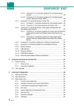
DIGIFORCE® 9307 4.4.3.7 Connector A, B: Connection guidance for normalized-signal 4.4.3.8 Connector A, B: Connection guidance for normalized-signal 4.4.4.1 Connector C: Connection guidance for incremental sensors ...49 4.4.5 Connector D: Incremental sensors, strain gage, potentiometer and 4.4.5.1 Connector D: Connection guidance for torque sensors that have 4.4.5.2 Connector D: Connection guidance for strain-gage torque
Open the catalog to page 6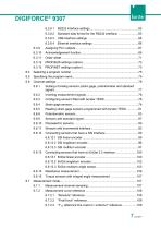
6.6.1 Scaling of analog sensors (strain gage, potentiometer and standard
Open the catalog to page 7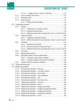
6.8.1.3 Additional results when recording two curves Y1(x) and Y2(x)123 6.8.2.2 Additional results when recording two curves Y1(x) and Y2(x)130 6.8.3.3 Additional results when recording two curves Y1(x) and Y2(x)137
Open the catalog to page 8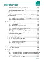
6.12.1 Parameters in „Sensor test" for channel X, Y1 und Y2 menu (menu 36)170 9.1.1 Changing the measurement program without program acknowledgement198 9.1.2 Changing the measurement program with program acknowledgement199
Open the catalog to page 9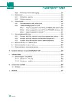
9.4.2.1 Switching signals for channel “X“ with ABSOLUTE reference205 9.4.2.2 Switching signals for channel “X“ with TRIGGER reference ..206
Open the catalog to page 10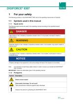
DIGIFORCE® 93071 For your safety ® The following symbols on the DIGIFORCE 9307 and in this operating manual warn of hazards. 1.1 Symbols used in this manual The following signal words are used in the operating manual according to the specified hazard classification. DANGER High degree of risk: indicates a hazardous situation which, if not avoided, will result in death or serious injury. Moderate degree of risk: indicates a hazardous situation which, if not avoided, may result in death or serious injury. Low degree of risk: indicates a hazardous situation which, if not avoided, could result in...
Open the catalog to page 11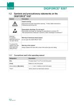
DIGIFORCE® 93071.2 Symbols and precautionary statements on the DIGIFORCE® 9307 Symbol
Open the catalog to page 12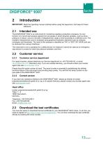
IMPORTANT: Read the operating manual carefully before using the equipment, and keep for future reference. The DIGIFORCE 9307 is an instrument for monitoring repetitive production processes. Its core function is to record and analyze signals from processes in which physical variables, such as force, pressure or torque, vary as a function of displacement, angle or time according to a defined curve. The resultant measurement curve is analyzed using graphical evaluation elements such as windows, envelopes and thresholds. The result of the analysis is classified as "OK" or "NOT OK" (NOK) and can be...
Open the catalog to page 13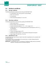
DIGIFORCE® 93072.4 Ambient conditions2.4.1 Storage conditions The following requirements must be met when storing the DIGIFORCE 9307: • The DIGIFORCE 9307 must be packed in clean packaging • Store at temperatures between 0° C and +60° C The following requirements must be met when operating the DIGIFORCE 9307: • Always operate indoors • Maximum height: above sea level 2000 m • Operate at temperatures between: +5 °C ... +40 °C, ideally +23 °C • Humidity: 80% up to +31 °C, decreasing flinearly above that temperature to 50% at Tmax, no condensation • Transient overvoltage category: CAT II • Potential...
Open the catalog to page 14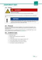
DANGER Electrical shock hazard Disconnect the DIGIFORCE® 9307 from the power plug before cleaning. Disconnect the DIGIFORCE 9307 from the power plug and use a slightly damp cloth for cleaning the unit. Do not immerse the DIGIFORCE 9307 in water or hold it under running water. Do not use strong cleaning agents as these may damage the DIGIFORCE® 9307. Use a slightly damp cloth to clean the DIGIFORCE® 9307. Personnel must be familiar with the relevant regulations. They must follow these regulations. Only trained personnel who are familiar with the applicable safety regulations are permitted to operate...
Open the catalog to page 15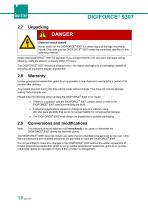
DANGER Electrical shock hazard ® Never switch on the DIGIFORCE 9307 if it shows signs of damage incurred in ® transit. Only ever use the DIGIFORCE 9307 under the conditions specified in this operating manual. ® Inspect the DIGIFORCE 9307 for damage. If you suspect that the unit has been damaged during shipping, notify the delivery company within 72 hours. ® The DIGIFORCE 9307 should be shipped only in its original packaging or in packaging capable of providing an equivalent degree of protection. burster praezisionsmesstechnik gmbh & co kg provides a manufacturer's warranty for a period of 24...
Open the catalog to page 16All Burster Measurement Solutions GmbH catalogs and technical brochures
 Operation Manual Model 8565
24 Pages
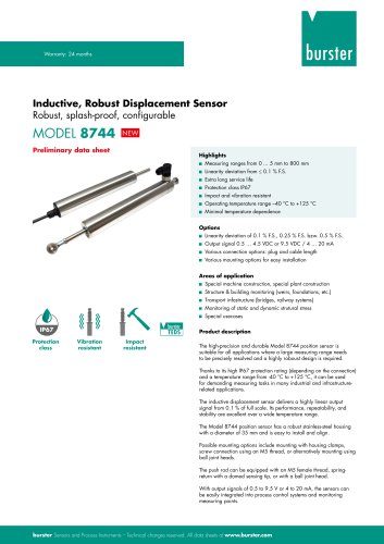 Data Sheet Model 8744
6 Pages
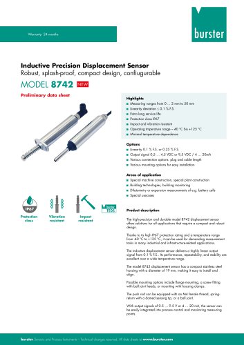 Data Sheet Model 8742
6 Pages
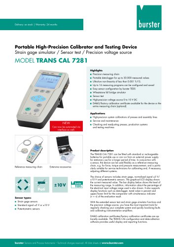 Data Sheet Model 7281
5 Pages
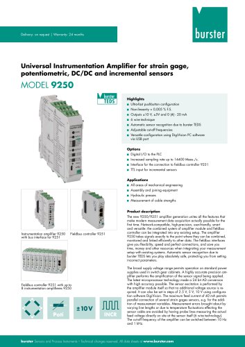 Data Sheet Model 9250
7 Pages
 Operation manual 2025
76 Pages
 Data Sheet Model 8523 (2025)
8 Pages
 Data-Sheet- Model 8228
6 Pages
 Data Sheet Model 8656
7 Pages
 Brochure Load Cell
25 Pages
 Data Sheet Model 8510 (2025)
5 Pages
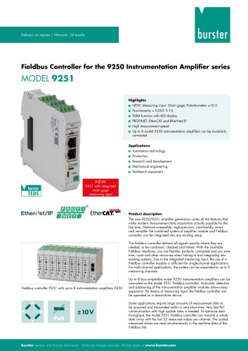 Data-Sheet - 9251
6 Pages
 Data sheet Model 8631
5 Pages
 Data Sheet Model 2511
6 Pages
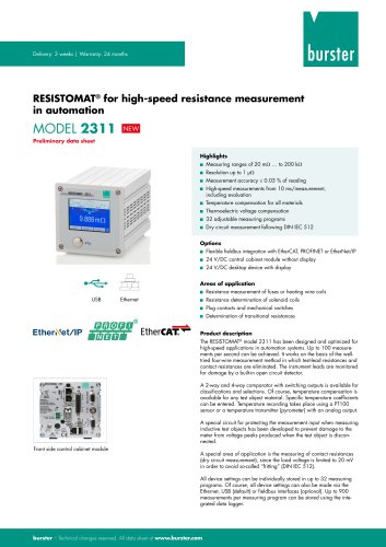 Data Sheet Model 2311
5 Pages
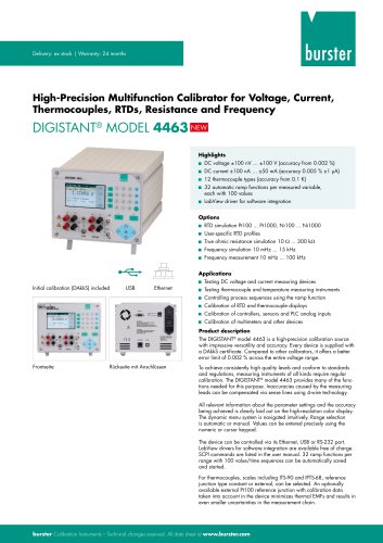 Data Sheet Model 4463
5 Pages
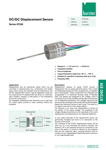 Data Sheet Typ 87240
2 Pages
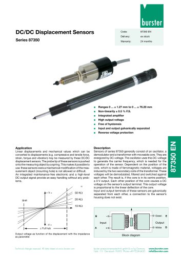 Data Sheet Series 87350
2 Pages
 Data Sheet Model 8630
6 Pages
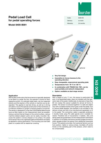 Data Sheet Model 8400-B001
2 Pages
 Load-cell
25 Pages
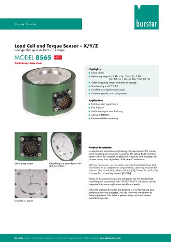 Data Sheet Model 8565
5 Pages
 Torque Sensors
9 Pages
 Data Sheet Typ 8625
7 Pages
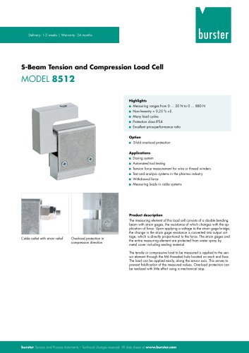 Data Sheet Typ 8512 (2025)
5 Pages
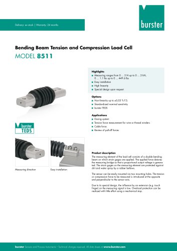 Data Sheet Model 8511 (2025)
6 Pages
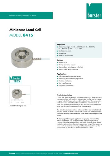 Data Sheet Model 8415 (2025)
6 Pages
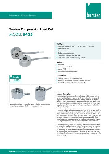 Data sheet Model 8435 (2025)
7 Pages
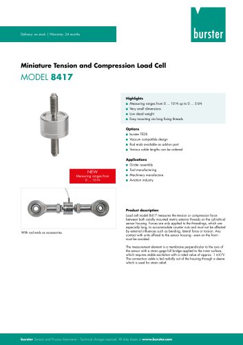 Data Sheet Typ 8417 (2025)
7 Pages
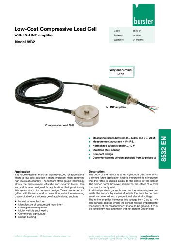 Data Sheet Typ 8532 (2025)
2 Pages
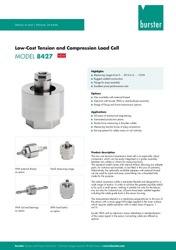 Data Sheet 8427 (2025)
7 Pages
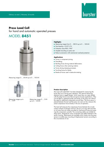 Data Sheet Motel 8451 (2025)
7 Pages
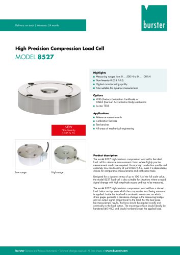 Data Sheet Model 8527 (2025)
7 Pages
 Data Sheet Model 8526 (2025)
9 Pages
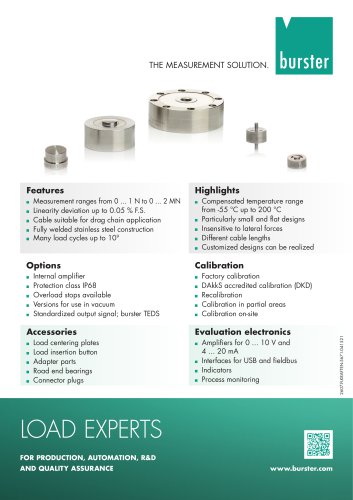 Flyer Load Experts 2025
1 Page
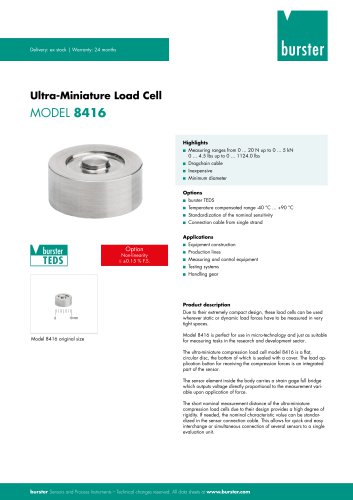 Data sheet Typ 8416 (2025)
6 Pages
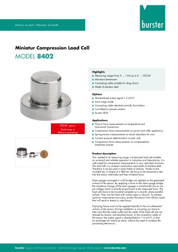 Data Sheet Model 8402 (2025)
6 Pages
 2511 BATTERY MEASURING MODULE
14 Pages
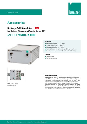 Data Sheet- Model 2500-Z100
2 Pages
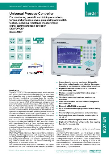 Data Sheet Typ 9307
6 Pages
 Data Sheet Model 9210
5 Pages
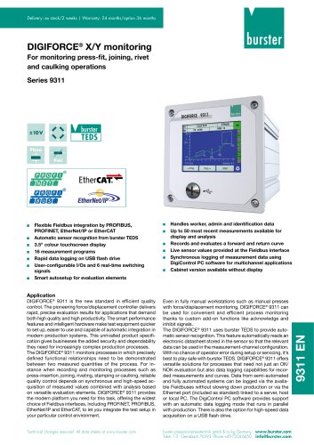 Data Sheet Typ 9311
6 Pages
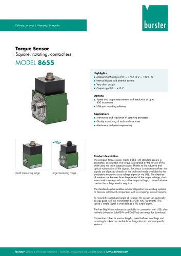 Data Sheet Typ 8655 (2025)
7 Pages
 Displacement Sensors 2025
2 Pages
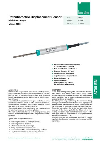 Data sheet Model 8709 (2025)
2 Pages
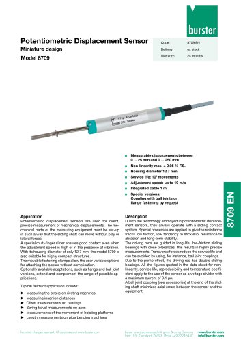 Data sheet Model 8709
2 Pages
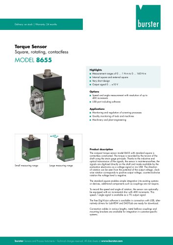 Data Sheet Typ 8655
7 Pages
 Data Sheet Model 8524
8 Pages
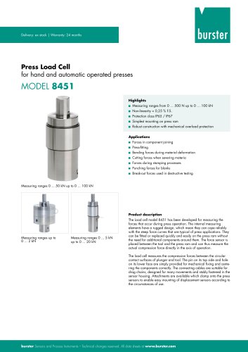 Data Sheet Motel 8451
7 Pages
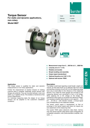 Data Sheet Typ 8627
2 Pages
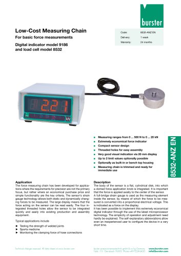 Data Sheet Model 9186/8532
2 Pages
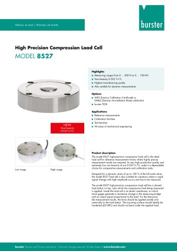 Data Sheet Model 8527
7 Pages
 Data Sheet Typ 8512
5 Pages
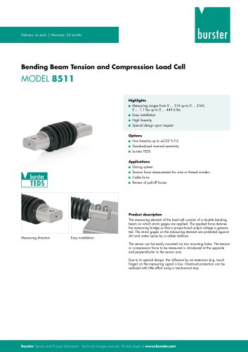 Data Sheet Model 8511
6 Pages
 Data Sheet Typ 8625
7 Pages
 Data Sheet Typ 8532
2 Pages
 Data Sheet Model 8561
6 Pages
 Data Sheet Model 8510
5 Pages
 Data Sheet Model 8523
8 Pages
 Data Sheet Model 8526
9 Pages
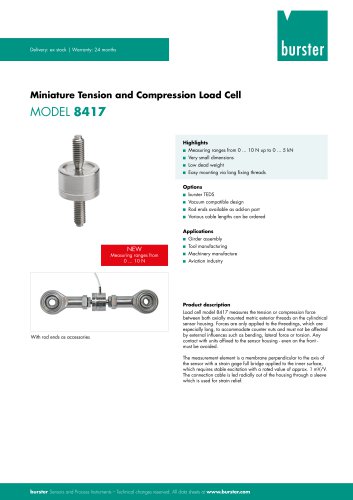 Data Sheet Typ 8417
7 Pages
 Data Sheet - Model 8438
6 Pages
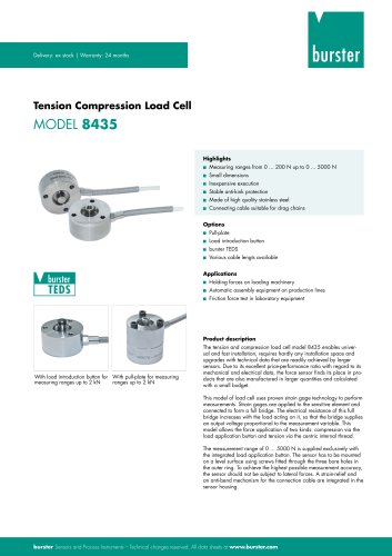 Data sheet Model 8435
7 Pages
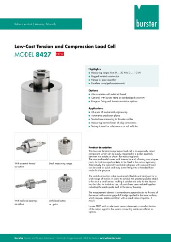 Data Sheet 8427
7 Pages
 Data Sheet Model 8402
6 Pages
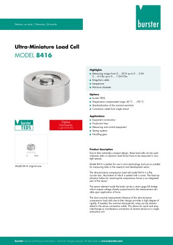 Data sheet Typ 8416
6 Pages
 Press fitting - the reliable way
11 Pages
 Data Sheet Model 9243
2 Pages
 Displacement Sensors
2 Pages
 Flyer Load Experts
1 Page
 Sensor Solutions
1 Page
 Data Sheet Model 9235
2 Pages
 Data sheet Series 8738
2 Pages
 Flyer Battery Tester
1 Page
 Data Sheet Model 2560
5 Pages
 Operation manual
76 Pages
 Data Sheet Typ 8739
2 Pages
 RESISTOMAT® Model 2329
4 Pages
 Data Sheet Model 2550
4 Pages
 Data Sheet Typ 8645
5 Pages
 Flyer Displacement Sensor
2 Pages
 Data Sheet - Model 8670
4 Pages




























Archived catalogs
 Data Sheet Model 8415
6 Pages

- BURSTER load cell
- Pressure transmitter
- BURSTER tension/compression load cell
- BURSTER steel load cell
- Calibration system
- Analog pressure transmitter
- BURSTER strain gauge load cell
- Digital indicator
- BURSTER stainless steel load cell
- Waterproof pressure transmitter
- Membrane pressure transmitter
- Stainless steel pressure transmitter
- Panel panel meter
- Relative pressure transmitter
- Position transducer
- Beam type force sensor
- Signal amplifying integrated circuit
- BURSTER compression load cell
- Automated software