
- Catalogs
- burster Measurement Solutions GmbH
- Oberation Manual - Sensor-Profibus-Modul 9221

Oberation Manual - Sensor-Profibus-Modul 9221

Oberation Manual - Sensor-Profibus-Modul 9221
- This manual provides essential information on the operation, installation, and configuration of the Sensor Profibus Module type 9221, available in IP20 and IP65 versions.
- Users must adhere to the instructions and technical data to avoid faults, incorrect measurements, or potential risks.
- Upon unpacking, verify all items are present and inspect for any shipping damage.
- The standard package includes the Sensor Profibus Module, a CD-ROM with configuration software, and a manual.
- The Sensor Profibus Module 9221 is designed for acquiring and processing sensor signals and digital status information, producing digital signals for the Profibus fieldbus level.
- It supports mechanical variable measurements such as force, torque, pressure, acceleration, displacement, and angle.
- Signal conditioning parameters can be set via software, eliminating the need for external amplifiers.
- Features include arithmetic averaging, input-signal filtering, zero calibration, MIN/MAX memory, and thresholds, with a communication speed of up to 12 Mbaud.
- The module provides stable sensor supply voltage and stores calibration data in EEPROM to prevent data loss during power failure.
- It includes d.c. isolation and three LEDs indicating operating status.
- Up to 127 modules can be connected to the Profibus line, with configuration and programming possible via a PC or PLC.
- The module is suitable for high-speed control functions and real-time operations, integrating analog sensor outputs into complex automation structures.
- Developed for high-speed control and real-time operations, suitable for industrial automation and test-bench technology.
- Features secure transmission protocol, high transmission rate, and simple design, making it ideal for industrial environments.
- Industry-compatible connection and installation technologies facilitate integration into existing systems.
- Teach-in Method: Involves setting lower and upper scale values by applying known weights.
- Using Test Certificate: Direct entry of sensor data from the certificate into the Sensor Profibus Module.
- Precision Voltage Source: Simulates sensor output using a precision voltage source.
- Shunt Resistance: Least accurate, used for occasional checks by unbalancing the bridge with a shunt resistor.
- Measuring Mode: Options include DC, DC-R (ratiometric), and ALT-R (ratiometric).
- Mean Values: Range from 1 to 6500.
- Evaluation Criteria: Includes upper and lower limits, and evaluation type (dynamic or static).
- Input Functions: Various functions such as perform tare, clear tare, reset evaluation, and inhibit evaluation are supported for both Input A and B.
- Evaluation Results: Results can be OK, too high, or too low.
- Sensor Test: Includes measuring and setting reference and tolerance values.
- Reset Functions: Options to reset evaluation results and value buffers.
- Tare: Measure and set new tare values.
- Measured Values: Includes ADC and calibrated measured values.
- Names: Station and program names can be set.
- Floating-Point Representation: Explained using IEEE-754-1985 standard with examples.
- Calculation Tips: Detailed steps for calculating floating-point values using bit manipulation.
- Display of Measurement Results: Discusses quantization errors and ADC usage.
- Increasing Resolution: Achieved through averaging and filtering.
- Optimum Device Configuration: Recommendations for sensor and device settings.
- Configuration software (type 9221-P001)
- Module power supply (type 9244-Z001)
- Data cable for PC connection (type 9900-K333)
- Various connectors for PLC interface (types 9900-V181, 9900-V225, 9900-V525)
- Snap-fit rail-mounting kit (type 9221-Z001)
- Calibration service for measuring chain (type 9221-Z001)
Catalog excerpts

OPERATION MANUAL © 2005 burster präzisionsmeßtechnik gmbh & co kg All rights reserved Stand 23.8.2005 Manufacturer: burster präzisionsmeßtechnik gmbh & co kg Talstraße 1-5 PO Box 1432 76593 Gernsbach 76587 Gernsbach The following information may be amended without notice. No part document may be reproduced or processed using electronic systems without prior consent in writing. burster provides no warranty of any kind with respect to this material, including the implied warranty of merchantable quality and fitness for purpose. burster is not liable under any cicumstances for errors, incidental damage or consequential loss sustained in connection with the function or use of this material.
Open the catalog to page 1
1. General preliminary remarks 4. Operating instructions for the IP20 version 5. Operating instructions for the IP65 version
Open the catalog to page 2
1.1 About this manual This equipment manual contains important information on the operation, installation and configuration of the Sensor Profibus Module type 9221, IP20 and IP65 versions. Note that the Sensor Profibus module type 9221 must be used in accordance with the instructions, technical data and conditions of use listed in this manual. If handled improperly or used incorrectly, one cannot rule out the possibility of faults, incorrect measurements, effects on or from other equipment and installations or potential risks to life and property. Please note the specific requirements that must...
Open the catalog to page 6
Equipment function The Sensor Profibus Module type 9221 is intended for the acquisition and processing of sensor signals and digital status information and for producing digital signals for the fieldbus level (Profibus). The Sensor Profibus Module is a user-configurable, single-channel module operated via an RS232 interface (configuration only) or RS485 interface (Profibus-DPV1). The universal Sensor Profibus Module is ideally suited to measuring mechanical variables such as force, torque, pressure, acceleration, displacement and angle. Acquisition and processing of strain-gage, potentiometric...
Open the catalog to page 7
The Sensor Profibus Module type 9221 has been specifically developed for highspeed control functions and real-time operations, and therefore covers a huge range of applications. The instrument has been designed to integrate the maximum possible range of analog sensor output signals into complex, networked and distributed automation structures. Thanks to its secure and reliable transmission protocol, its high transmission rate and its simple design, the module is perfectly qualified for use in both industrial automation engineering and test-bench technology. Exploiting the instrument's quick response...
Open the catalog to page 8
Operating instructions for the IP20 version Installation / Fixing The Sensor Profibus Module type 9221 has a snap-fit design for mounting on a standard 35 mm DIN (top-hat) rail to DIN EN 50022. The unit is fixed to the DIN rail via a clip on its rear side. First place the clip on the DIN rail from above and then press the module down onto the DIN rail until the lower edge of the clip snaps onto the DIN rail. For optimum measurement quality the DIN rail must be grounded. To remove the module, once again push down on the module from above while tilting the lower edge of the clip forwards to release...
Open the catalog to page 11
Front view Input / Output Status LEDs Supply voltage Profibus port (RS485) Sensor connection Rear view Address setting Fixing clip for DIN-rail mounting Terminal assignments Wires are connected via screw terminals on the module. All terminal blocks have a plug-in design, so they can be removed from the module for convenient cable connection. No more than two wires should be connected to one terminal. Ferrules are recommended for connecting stranded wires. Shielded cables must be used for the voltage-supply lines and signal conductors to avoid interference on sensor signals or in the module. Page...
Open the catalog to page 12
The Sensor Profibus Module type 9221 has four mounting holes for fixing the module in place. The module must only be installed by a qualified person. The Sensor Profibus Module type 9221 has IP65 degree of protection. The module is therefore protected against ingress of dust and water jets. The permitted ambient temperature range for the Sensor Profibus Module type 9221 during operation is 0 °C to +60 °C. The unit can be stored at temperatures between -30 °C and +85 °C. 5.4 Front panel / terminal assignments Front panel The following diagram shows the plan view of the Sensor Profibus Module with...
Open the catalog to page 13
Plan view Status LEDs Plan view Mounting holes Configuration interface (RS232) Address setting Supply voltage Profibus terminating resistance Sensor Input connectio n Profibus port (RS485) – B-coded
Open the catalog to page 14
Terminal assignments Cables are connected via PG cable glands and screw terminals on the module. All terminal blocks have a plug-in design, so they can be removed from the module for convenient cable connection. No more than 2 wires should be connected to one terminal. Ferrules are recommended for connecting stranded wires. Shielded cables must be used for the voltage-supply lines and signal conductors to avoid interference on sensor signals or in the module. 4: Signal input 3: Signal input + 2: Sensor + 1: Excitation + 3: Ground 24 V 2: Protective ground 7 (10): Monitor output ground 6 (9):...
Open the catalog to page 15
Block diagram and internal signal processing Voltage supply Profibus Asic Monitor Output The A/D converter amplifies and converts the signals according to the design and type of the connected sensor. The A/D converter digitizes all incoming signals with a resolution of 16 bits. The analog multiplexer and A/D converter are controlled by the microprocessor. The A/D converter contains an amplifier with various amplifier stages. The gain and the corresponding accuracy and resolution of the measured value depends on the measuring range selected. In addition, there is an option for arithmetic averaging...
Open the catalog to page 16
Before applying the supply voltage to the sensor module, make a final check that the unit is installed correctly and set to the correct voltage. It is essential to check that the unit has been grounded in accordance with regulations and that the supply voltage for all the Sensor modules does not exceed the specified + 36 VDC. 6.4 Terminal assignments 6.5 Supply voltage The Sensor Profibus Module can be supplied with 20 - 36 VDC (d.c. supply) or with 14 - 26VAC (a.c. supply). The instrument has its own internal protection to safeguard the supply input against overvoltage, overcurrent and polarity...
Open the catalog to page 17All Burster Measurement Solutions GmbH catalogs and technical brochures
 Operation Manual Model 8565
24 Pages
 Data Sheet Model 8744
6 Pages
 Data Sheet Model 8742
6 Pages
 Data Sheet Model 7281
5 Pages
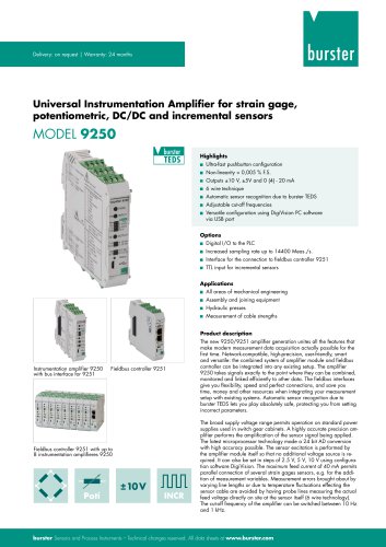 Data Sheet Model 9250
7 Pages
 Operation manual 2025
76 Pages
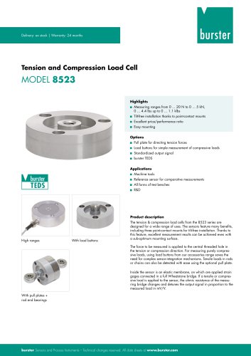 Data Sheet Model 8523 (2025)
8 Pages
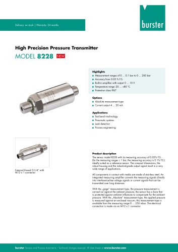 Data-Sheet- Model 8228
6 Pages
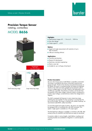 Data Sheet Model 8656
7 Pages
 Brochure Load Cell
25 Pages
 Data Sheet Model 8510 (2025)
5 Pages
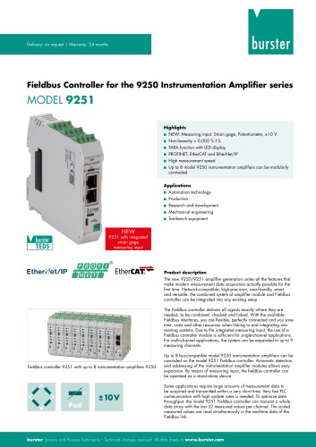 Data-Sheet - 9251
6 Pages
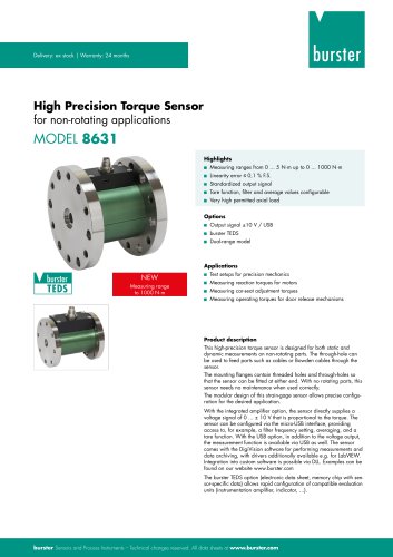 Data sheet Model 8631
5 Pages
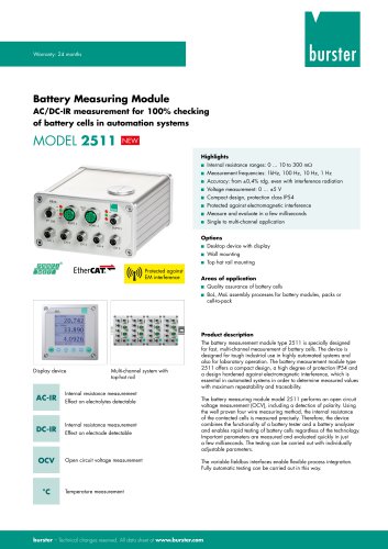 Data Sheet Model 2511
6 Pages
 Data Sheet Model 2311
5 Pages
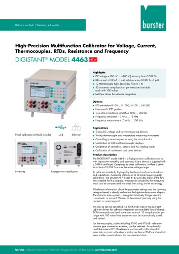 Data Sheet Model 4463
5 Pages
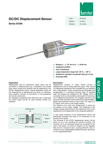 Data Sheet Typ 87240
2 Pages
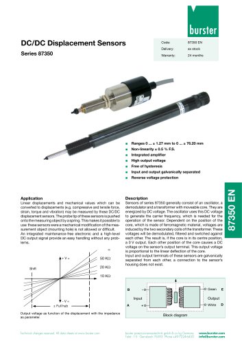 Data Sheet Series 87350
2 Pages
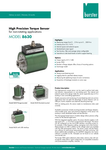 Data Sheet Model 8630
6 Pages
 Data Sheet Model 8400-B001
2 Pages
 Load-cell
25 Pages
 Data Sheet Model 8565
5 Pages
 Torque Sensors
9 Pages
 Data Sheet Typ 8625
7 Pages
 Data Sheet Typ 8512 (2025)
5 Pages
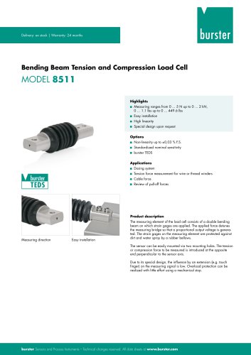 Data Sheet Model 8511 (2025)
6 Pages
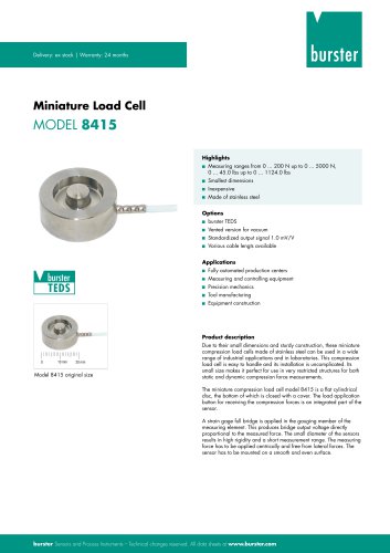 Data Sheet Model 8415 (2025)
6 Pages
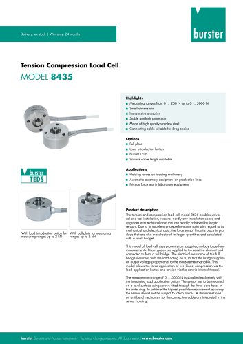 Data sheet Model 8435 (2025)
7 Pages
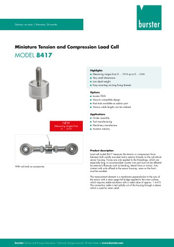 Data Sheet Typ 8417 (2025)
7 Pages
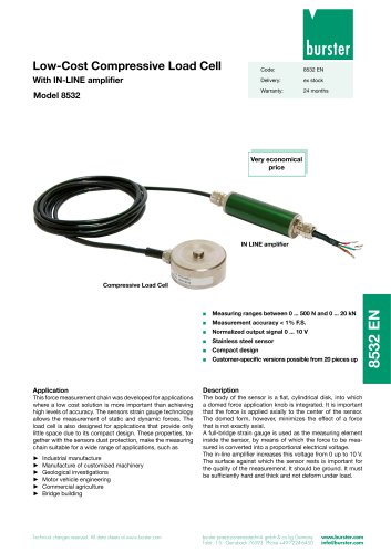 Data Sheet Typ 8532 (2025)
2 Pages
 Data Sheet 8427 (2025)
7 Pages
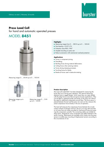 Data Sheet Motel 8451 (2025)
7 Pages
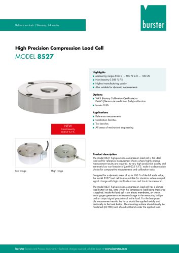 Data Sheet Model 8527 (2025)
7 Pages
 Data Sheet Model 8526 (2025)
9 Pages
 Flyer Load Experts 2025
1 Page
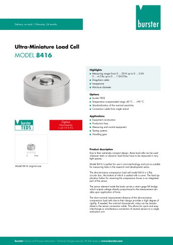 Data sheet Typ 8416 (2025)
6 Pages
 Data Sheet Model 8402 (2025)
6 Pages
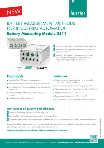
 2511 BATTERY MEASURING MODULE
14 Pages
 Data Sheet- Model 2500-Z100
2 Pages
 Data Sheet Typ 9307
6 Pages
 Data Sheet Model 9210
5 Pages
 Data Sheet Typ 9311
6 Pages
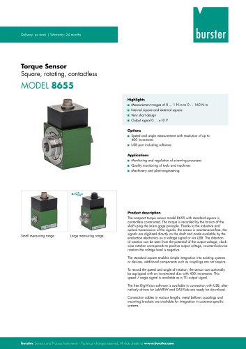 Data Sheet Typ 8655 (2025)
7 Pages
 Displacement Sensors 2025
2 Pages
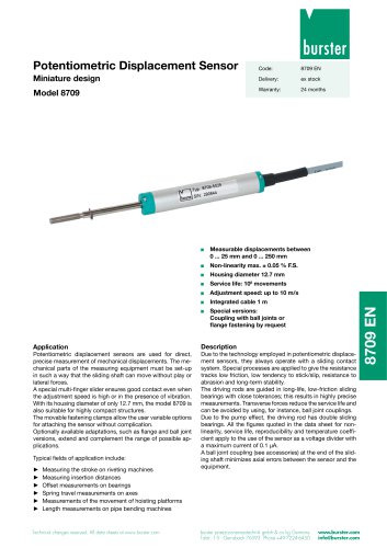 Data sheet Model 8709 (2025)
2 Pages
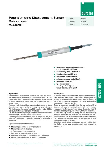 Data sheet Model 8709
2 Pages
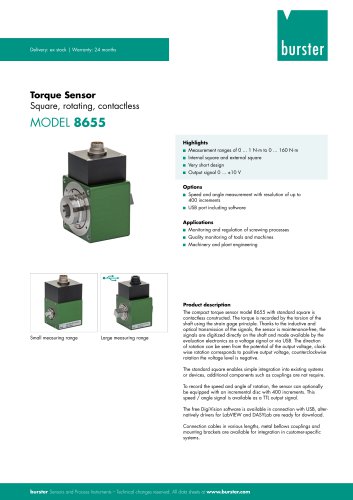 Data Sheet Typ 8655
7 Pages
 Data Sheet Model 8524
8 Pages
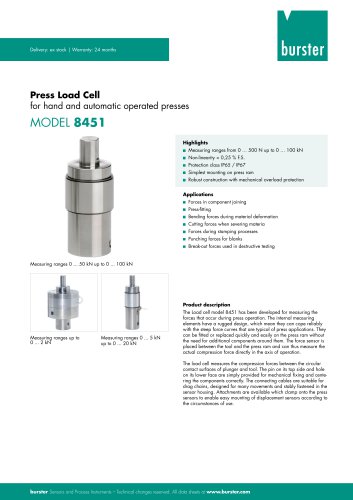 Data Sheet Motel 8451
7 Pages
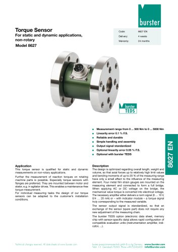 Data Sheet Typ 8627
2 Pages
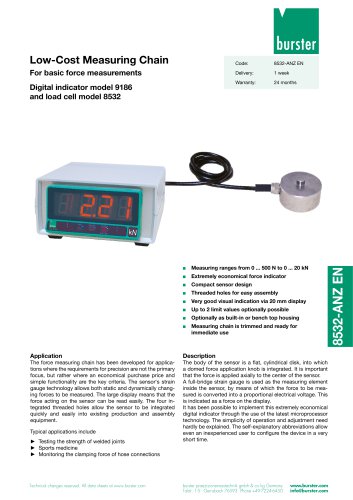 Data Sheet Model 9186/8532
2 Pages
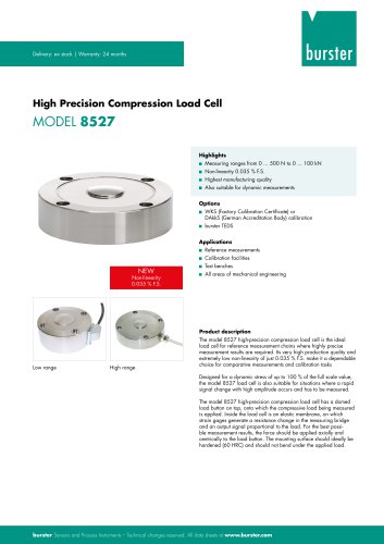 Data Sheet Model 8527
7 Pages
 Data Sheet Typ 8512
5 Pages
 Data Sheet Model 8511
6 Pages
 Data Sheet Typ 8625
7 Pages
 Data Sheet Typ 8532
2 Pages
 Data Sheet Model 8561
6 Pages
 Data Sheet Model 8510
5 Pages
 Data Sheet Model 8523
8 Pages
 Data Sheet Model 8526
9 Pages
 Data Sheet Typ 8417
7 Pages
 Data Sheet - Model 8438
6 Pages
 Data sheet Model 8435
7 Pages
 Data Sheet 8427
7 Pages
 Data Sheet Model 8402
6 Pages
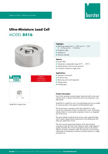 Data sheet Typ 8416
6 Pages
 Press fitting - the reliable way
11 Pages
 Data Sheet Model 9243
2 Pages
 Displacement Sensors
2 Pages
 Flyer Load Experts
1 Page
 Sensor Solutions
1 Page
 Data Sheet Model 9235
2 Pages
 Data sheet Series 8738
2 Pages
 Flyer Battery Tester
1 Page
 Data Sheet Model 2560
5 Pages
 Operation manual
76 Pages
 Data Sheet Typ 8739
2 Pages
 RESISTOMAT® Model 2329
4 Pages
 Data Sheet Model 2550
4 Pages
 Data Sheet Typ 8645
5 Pages
 Flyer Displacement Sensor
2 Pages
 Data Sheet - Model 8670
4 Pages
























Archived catalogs
 Data Sheet Model 8415
6 Pages

- BURSTER load cell
- Pressure transmitter
- BURSTER tension/compression load cell
- BURSTER steel load cell
- Calibration system
- Analog pressure transmitter
- BURSTER strain gauge load cell
- Digital indicator
- BURSTER stainless steel load cell
- Waterproof pressure transmitter
- Membrane pressure transmitter
- Stainless steel pressure transmitter
- Panel panel meter
- Relative pressure transmitter
- Position transducer
- Beam type force sensor
- Signal amplifying integrated circuit
- BURSTER compression load cell
- Automated software