8041
1 /10Pages

8041
1 /10Pages
Catalog excerpts

Insertion magnetic inductive flowmeter • Sensor without moving parts • Flowmeter with On/Off control • Application related calibration by Teach-In function • Clean in place (CIP) • FDA-compliant materials Type 8041 can be combined with… Type 8025 Insertion flowmeter or batch controller (remote version) Type 8802 ELEMENT continuous control valve systems The electromagnetic flowmeter 8041 is made up of an electronic module and a sensor consisting of PVDF or stainless steel material. It has been designed to measure a flow rate of neutral and slightly aggressive fluids with a conductivity of more than 20 µS/cm in DN06…DN400 pipes. It is fitted with a 4…20 mA output, a pulse output and a relay output. The different parameters can be set by means of 5 DIP switches, a push-button and a 10- field LED bargraph. It is available: - ith G 2" connection for the version with a w PVDF sensor - ith G 2" or clamp connection for the verw sion with a stainless steel sensor. The version with a stainless steel sensor can be used in applications with higher pressures (PN16) and higher temperatures (150 °C). Type 8619 multiCELL - Transmitter/controller Type 8644 Remote process actuation control system AirLINE General data Compatibility Materials Housing, cover, nut P VDF sensor version Stainless steel sensor version S crews Seal Cable glands Wetted parts materials S ensor holder Electrodes Seals Earth ring (PVDF sensor version) Electrode holder (St. Steel sensor version) Surface finishing quality Electrical connections Recommended cable with fittings S020 (see corresp. datasheet) PC (glass fibre reinforced for housing) PPA (glass fibre reinforced) Stainless steel NBR A with neoprene seal PVDF or Stainless steel 1.4404/316L Stainless steel 1.4404/316L G 2" connection: FKM or EPDM (conform to FDA), Clamp connection: EPDM or FEP (to be ordered separately) Stainless steel 1.4404/316L PEEK (conform to FDA) Ra < 0.8 µm (Clamp connection) 2 cable glands M20 × 1.5 0.5…1.5 mm2 cross-section, shielded cable, 6…12 mm diameter (if only one cable is used per cable gland) or 4 mm diameter (if two cables are used per cable gland with using the supplied multi-way seal) Environment Ambient temperature Relative humidity Height above sea level
Open the catalog to page 1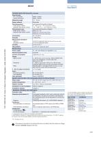
Complete device data (Fitting S020 + flowmeter) Pipe diameter G 2" connection Clamp connection Measuring range Sensor element Fluid temperature PVDF sensor version Stainless steel sensor version Fluid pressure max. PVDF sensor version Stainless steel sensor version Conductivity see Pressure/Temperature diagram 0…+80 °C (+32…+176 °F) (depends on fitting) -15…+150 °C (+5…+302 °F) (depends on fitting) see pressure/temperature diagram PN10 (145.1 PSI) PN10 (145.1 PSI) (with plastic fitting) PN16 (232.16 PSI) (with metal fitting) min. 20 µS/cm Measurement deviation1) Teach-In Standard K-factor Linearity...
Open the catalog to page 2
8041 Pressure/Temperature diagram Please be aware of the fluid pressure/temperature dependence according to the respective fitting+flowmeter material as shown in the diagrams. (depending on the fitting material) 8041 with a stainless steel sensor (depending on the fitting material) 8041 with a PVDF sensor A: Application range for complete device (fitting + flowmeter) Main features and programming Using as a flowmeter • rogramming of the full scale P - selection of a predefined measuring range: 0…2, 0…5 or 0…10 m/s - selection by Teach-In: with the actual max. flow velocity of the application...
Open the catalog to page 3
8041 Design The E-shaped magnetic system inside the sensor induces a magnetic field into the fluid, which is perpendicular to the direction of flow. Two electrodes are in galvanic contact with the liquid. Based on the Faraday law a voltage can be measured between these electrodes once a liquid (min. conductivity of 20 µS/cm) flows along the pipe. This voltage is proportional to the flow velocity. Using the K-factor for the individual pipe diameter the speed of flow is converted into volume per time. Display on PCB Terminal strip: - Power supply - 4…20 mA - Frequency output Green LED: - flashing...
Open the catalog to page 4
Installation The 8041 flowmeter can easily be installed into any Bürkert Insertion fitting system (S020) by just fixing the main nut. Minimum straight upstream and downstream distances must be observed. According to the pipe’s design, necessary distances can be bigger or use a flow conditioner to obtain the best accuracy. Fore more information, please refer to EN ISO 5167‑1. EN ISO 5167‑1 prescribes the straight inlet and outlet distances that must be 50 x DN 5 with when installing fittings in pipe linesxin order to complied x DN 25 DN 5 x DN achieve calm flow conditions. The most important layouts...
Open the catalog to page 5
8041 Diagram Flow rate/Velocity/DN Example: • Flow: 10 m3/h • Ideal flow velocity: 2…3 m/s For these specifications, the diagram indicates a pipe size of DN40 [or DN50 for (*) mentioned fittings] Flow rate of uid US gpm 20000 10000 5000 Flow velocity * for following fittings with: • external thread acc. to SMS 1145 • eld end acc. to SMS 3008, BS 4825‑1/ASME BPE/DIN 11866 series C or DIN 11850 series 2/DIN 11866 series A/DIN EN 10357 series A w • Clamp acc. to SMS 3017, BS 4825‑3/ASME BPE
Open the catalog to page 6
8041 Dimensions [mm] G 2" connection version 116 Plastic spigot Metal spigot Note: The length of the sensor finger depends on the fitting used. See data sheet Type S020 or available fitting DN diagram on page 10. Clamp connection version 116
Open the catalog to page 7
8041 Ordering information and chart for flowmeter Type 8041 • G 2" connection to use with S020 Fitting for flowmeter with G 2" connection. A complete flowmeter Type 8041 with G 2" connection consists of a flowmeter Type 8041 (with G 2" connection) and a Bürkert fitting Type S020. The following information is necessary for the selection of a complete device: Article no. of the desired flowmeter Type 8041 (see ordering chart, below) • •Article no. of the selected fitting Type S020 for flowmeter with G 2" connection (see separate data sheet) Certificates Relay short, stainless steel long, stainless...
Open the catalog to page 8All BÜRKERT FLUID CONTROL SYSTEMS catalogs and technical brochures
 Type 0121
16 Pages
 Type 6240
26 Pages
 Type 8020
10 Pages
 Type 8026
12 Pages
 Type 8605
13 Pages
 Type 8692
18 Pages
 Type 5470
15 Pages
 Type 0498
6 Pages
 Type 8081
9 Pages
 Type 2300
32 Pages
 Type 8012
21 Pages
 Type 8110
11 Pages
 Type 8010
14 Pages
 8222
82228 Pages
 Type 8137
12 Pages
 Typ 8804
12 Pages
 Product Overview MicroFluidics
18 Pages
 Proportional Valves
17 Pages
 Process and Control Valves
39 Pages
 Measurement devices
68 Pages
 S.EV series solenoid valves
16 Pages
 Pivoted armature valve 330
13 Pages
 Solenoid valves 6240
9 Pages
 Solenoid Valves
31 Pages
 6240
624011 Pages
 Type 0301
4 Pages
 Type 0201
4 Pages
 Type 0300
6 Pages
 Type 0200
6 Pages
 Type 0131
4 Pages
 Type 0142
4 Pages
 Type 0117
3 Pages
 Type 0293
3 Pages
 Process & Control Valves
33 Pages
 Diaphragm Competence
14 Pages
 Standard Product Program
13 Pages
 AirLINE SP
2 Pages
 multiCELL Type 8619
5 Pages
 Flowmeter Type 8045
4 Pages
 eControl Type 8611
2 Pages
 Dosing Systems
4 Pages
 Micro Valve: Whisper Valve
5 Pages
 Mass Flow Controllers for Gases
16 Pages
 Industrie-Flyer Food_En
4 Pages
 Industrial Inkjet Printing
2 Pages
 Flyer Hygienic Processing Pharma
32 Pages
 Food and Beverage
32 Pages
 Systemhaus Brochure
8 Pages
 Flyer Cooking
2 Pages
 Clean Steam
2 Pages
 Injection Molding
2 Pages
 Heat Exchanger
2 Pages
 Cooling Towers
2 Pages
 Fuel Cell Tech
2 Pages
 Robot Welding
2 Pages
 Plastic Extrusion Lines
2 Pages
 Plastic Extruding
2 Pages
 MicroFluidics Brochure
16 Pages
 Segment Brochure Gas Handling
17 Pages
 Company profile
15 Pages
 CUT Product Line
9 Pages
 CATALOGUE BURKERT SELECT
88 Pages
 MicroFluidics
2 Pages
 Flyer Control Cabinet Solutions
16 Pages
 Water Treatment Brochure
16 Pages
 Product Catalogue:Bürkert Select
88 Pages
 Cooling Systems Brochure
16 Pages
 steam products
16 Pages
 Product Overview Pneumatics
24 Pages
 Product overview Sensors
52 Pages


