


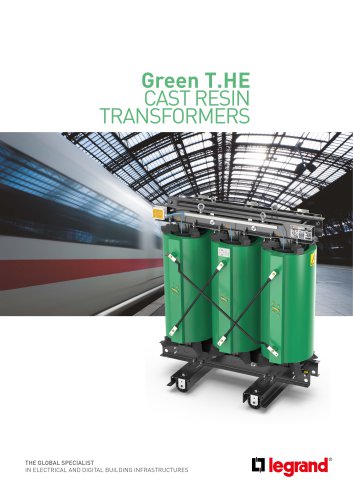
Cast Resin Transformers
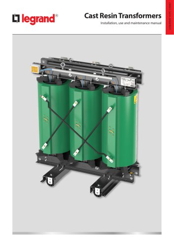
Cast Resin Transformers
Installation and use of cast resin transformers must comply with national and international standards to prevent risks such as electric shock or fire. The manual should be read thoroughly before installation, and operations should only be conducted when the transformer is not energized. Unauthorized modifications void warranties and liabilities.
The document references IEC standards, including the IEC 60076 series for power transformers and IEC 60529 for enclosure protection.
The rating plate provides nominal values and serial numbers. Proper operation requires adherence to manual instructions, correct earth connections, and protection against environmental and mechanical damage.
Transformers must be securely fixed during transport and inspected for damage upon receipt. Storage conditions should protect against environmental factors, with temperatures not falling below -25°C.
Transformers are designed for indoor installation in clean, dry environments, complying with IEC 60076-11 standards and national safety rules. Proper ventilation and positioning are critical to prevent overheating.
LV and HV connections require specific materials and techniques to prevent corrosion and ensure mechanical stability. Tightening torques are specified to prevent damage.
Proper ventilation is necessary to dissipate heat. The manual provides formulas to calculate required ventilation openings based on transformer losses.
Commissioning involves earth connections, voltage settings, and energizing procedures. Regular maintenance is essential, with guidelines for troubleshooting and customer care.
Surge arresters with appropriate technical characteristics must be installed to protect transformers from overvoltages. Equipment for power factor correction should have inrush current limiters.
Transformers should have temperature monitoring devices like Pt100 or PTC probes. Connection diagrams are provided, with recommended alarm and trip settings for different insulation systems.
Before energizing, checks must be performed, including verifying earth connections and temperature control devices. Voltage settings on HV windings can be adjusted using tappings.
Earth resistance measurements should be conducted with a Megohmmeter. If values are lower than expected, drying the transformer and contacting support may be necessary.
Sparkles near the magnetic core may occur upon connection but do not affect operation. Proper protection settings are crucial to prevent inrush current issues.
Regular maintenance includes checking temperature sensors, cleaning windings, and ensuring proper tightening of bolts. Frequency varies based on conditions and events.
- Overtemperature of a Single Winding: Check connection positions and replace faulty sensors.
- General Overheating: Clean blocked openings and check ventilation.
- Overheating in the Core: Contact technical assistance for support.
- Abnormal Noise: Verify voltage levels and use flexible connections.
- Alarm and Tripping Relay Activation: Replace sensors, reduce load, and ensure ventilation.
- Untimely Electrical System Protection Activation: Adjust protection settings carefully.
Contact customer service at +39 030 2017100 or [email protected] with the transformer's serial number for information or spare parts.
An exploded diagram lists components such as lifting eyes, core clamps, windings, and terminals.
Legrand optimizes transformers for simplicity, safety, and environmental performance, adhering to regulations and using new materials to minimize impact. A table outlines materials used, aiding recycling efforts.
A table details the weights of materials used in transformers by power range, aiding in recycling efforts.
Legrand reserves the right to modify the manual's contents and communicate changes as necessary.
Catalog excerpts
Cast Resin Transformers Installation, use and maintenance manual
Open the catalog to page 1
Cast Resin Transformers
Open the catalog to page 2
Cast Resin Transformers 3.1 Conditions for the correct operation of the transformer 4 Transport, receipt and storage 5.1.1 Installation in protection enclosure 5.1.2 Installation without protective enclosure (IP00) 5.1.3 Examples of wrong installation 5.2 Connections on the Low Voltage side - LV 5.3 Connections on the High Voltage side - HV 5.4 Tightening torque for electrical and mechanical connections 5.7 Protection against overvoltages 5.8 Temperature monitoring systems 6.2 Tappings for voltage setting on HV windings 6.4 Measurement of windings earth resistance 7 Reception, installation and...
Open the catalog to page 3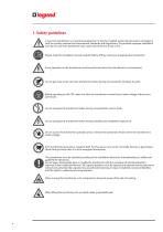
1. Safety guidelines A cast resin transformer is an electrical equipment. It must be installed, protected and used in compliance with the existing national and international Standards and Regulations. The possible improper installation and use of a cast resin transformer may cause risks of electric shock or fire. Please, read this installation manual carefully before: lifting, moving or energising the transformer. Every operation on the transformer must be performed when the transformer is not energised. Do not get close to the cast resin transformer before having connected the windings to earth....
Open the catalog to page 4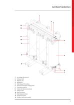
1312 1110 Installation, use and maintenance manual 1. Low Voltage Terminal (LV) 5. High Voltage (HV) winding 6. Horizontal movement hooking points 8. Trolley with bidirectional wheels 11. High Voltage Terminals 13. Auxiliary circuit box for probes
Open the catalog to page 5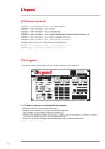
IEC 60076-11 - Power transformers - Part. 11: Dry-type transformer. IEC 60076-1 - Power transformers - Part 1: General. IEC 60076-2 - Power transformers - Part. 2: Temperature rise. IEC 60076-3 - Power transformers - Part 3: Insulation levels, dielectric tests and external clearances in air. IEC 60076-5 - Power transformers - Part. 5: Ability to withstand short circuit. IEC 60076-10 - Power transformers - Part. 10: Determination of sound levels. IEC 60085 - Electrical insulation - Thermal evalution and designation. IEC 60270 - High-voltage test techniques - Partial discharge measurements. IEC...
Open the catalog to page 6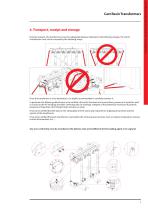
4. Transport, receipt and storage During transport, the transformers must be adequately fixed as indicated in the following images. HV and LV connections must not be stressed by the retaining straps. Once the transformer is at its destination, it is highly recommended to carefully examine it. In particular the following details have to be verified: HV and LV terminals and connections, presence of scratches and/ or cracks on the HV windings and their centering with LV windings, integrity of the protection enclosure (if present), presence of impurities, dirt, foreign body, moisture or water. It...
Open the catalog to page 7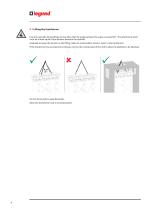
4.1 Lifting the transformer Use all 4 eye bolts during lifting. Do not allow that the angle between the ropes to exceed 60°. The attachment point must be at least equal to the distance between the eyebolts. Gradually increase the tension on the lifting cables to avoid sudden shock or stress to the transformer. If the transformer has a protective enclosure, remove the central panel of the roof to allow the eyebolts to be attached. Do not stand under suspended loads. Move the transformer only in vertical position.
Open the catalog to page 8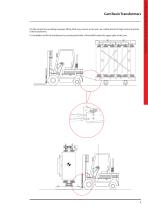
Lift the transformer avoiding improper lifting (that may cause it to tip over): be careful about the high centre of gravity of the transformer. It is forbidden to lift the transformer by inserting the forks of the forklift under the upper yoke of the core. Installation, use and maintenance manual Cast Resin Transformers
Open the catalog to page 9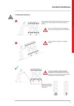
The transformer (with or without enclosure) must be moved using the track or lower jokes where the proper holes are located. Do not move the transformers by applying force on the windings or on their connections. Avoid moving the transformer on sloping surfaces. It is recommended to avoid moving the transformer on the wheels more than 10 m. Movement can be made only in two directions, according to the wheels orientation. Attachment points for horizontal movement using ropes. Installation, use and maintenance manual Cast Resin Transformers
Open the catalog to page 11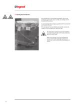
4.3 Storing the transformer If the transformer is not installed immediately, it has to be protected against water, dust, humidity and sunlight even if provided with enclosure. In case of storage the packaging supplied with the transformer must not be removed. If the transformer has been lifted using eyebolts, restore the integrity of the packaging with adhesive tape. The temperature during storage and installation must not decrease below -25°C (unless otherwise agreed at order stage). After a long storage at very low temperatures or in an environment with high humidity, the transformer must be...
Open the catalog to page 12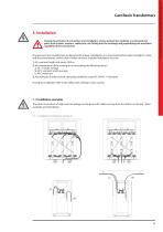
5. Installation During the activities of connection and installation, always protect the windings to avoid external parts such as bolts, washers, cable parts, etc. falling into the windings and jeopardizing the insulation capability of the transformer. Dry type cast resin transformers are designed for indoor installations, in a site protected from direct sunlight, in clean and dry environments, without risk of water intrusion. Standard installation must be: 1. At a sea level height not above 1000 m 2. At a temperature of the cooling air not exceeding the following values: a. 20 ° C yearly average...
Open the catalog to page 13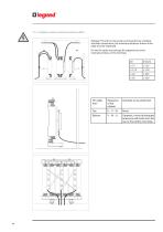
Between HV and LV connections and transformer windings and delta connections, the minimum distances shown in the table must be respected. HV and LV cables must always be supported to avoid mechanical stress on the terminals.
Open the catalog to page 14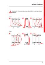
Cast Resin Transformers 5.1.3 c A High and Low Voltage connection cables must not be laid inside the delta and/or star connection and must not touch it. The connection cables must not touch the windings, or any other active parts of the transformer. Installation, use and maintenance manual
Open the catalog to page 15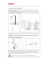
5.2 Connections on the Low Voltage side - LV LV terminals are positioned on the upper part of the transformer and they are made with aluminium bars without galvanic treatment as standard. We recommend to make the cable connection with tinned-copper cable terminals, connecting one or two cables in each hole. Before making the connection, thoroughly clean the contact surfaces with a special cleaner for electrical connections, making sure to dry them completely. In the case of connections with busbar it is necessary to use flexible connections to mechanically isolate the transformer from busbars....
Open the catalog to page 16All BTICINO catalogs and technical brochures
 AABBTV15
1 Page
 344625
1 Page
 Livinglight
136 Pages
 QUICK SELECTION GUIDE 2021
32 Pages
Archived catalogs

- Dry transformer
- Single-pole switch
- Push-button switch
- Circuit breaker
- Communication gateway
- IEC transformer
- Solderless terminal
- Fieldbus gateway
- Isolation transformer
- Industrial transformer
- Low-voltage transformer
- Wireless gateway
- Rotary electric switch
- Three-phase transformer
- DIN rail gateway
- IoT gateway
- Form push-button switch