- Catalogs
- BS&B SAFETY SYSTEMS, L.L.C.
- Introduction to Rupture Disk
Introduction to Rupture Disk
1 /14Pages

Introduction to Rupture Disk
1 /14Pages
Catalog excerpts

BS«B SAFE TV SYSTEMS, LXJt BSAB SAFETY SYSTEMS LTD.
Open the catalog to page 1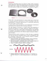
Predicting the failure point of a piece of metal within extremely close tolerances—after disturbing the grain structure by forming the metal into a dome—is phenomenal. The process of trans- forming a piece of metal into a rupture disk is shown in Figure 1. Since 1931. the requirements for rupture disks have varied from a remote pipeline installation to moon modules—and the acceleration of industrial requirements is continually advancing the technology of rupture disks. A rupture disk is best described as a non-mechanical overpressure relief device that ruptures when its rating is attained. The...
Open the catalog to page 2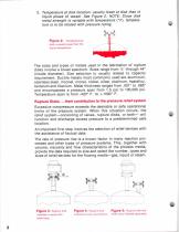
Temperature at disk location: usually lower at disk than in liquid phase of vessel. See Figure 2. NOTE: Since disk metal strength is variable with temperature ("F), tempera- ture is to be related with pressure rating. disk is usually lower than the liquid temperature. The sizes and types of metals used in the fabrication of rupture disks involve a broad spectrum. Sizes range from W through 44" (inside diameter). Size selection is usually related to capacity requirement. Ductile metals most commonly used are aluminum, stainless steel, inconel, monet, nickel, silver, platinum, hastelloy, tantalum...
Open the catalog to page 3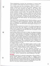
Three arrangements involving the incorporation of rupture disks into a pressure relief system are shown in Figures 3, 4 and 5. The in-series valve and disk combination shown in Figure 3 is usually classified as the primary relief device. Capacity is con- trolled by the valve—provided the design of the rupture disk assembly at valve inlet does not restrict the rate of flow. The rup- ture disk assembly isolates the valve from process media during normal operation of the system. The rupture disk serves as a barrier to prevent leakage. If process media has a high viscosity and its adherence to mechanical...
Open the catalog to page 4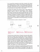
If an unrestricted overpressure relief area is required, the rupture disk assembly shown in Figure 4 may be used in the pressure sys- tem. If discharge piping is used, it must be adequately braced and supported. Piping load must not be imposed on the rupture disk. Any friction loss in the vent piping must be considered when sizing the relief area for the rupture disk or relief device. A primary relief system may consist of one or more rupture disk assemblies, rupture disk/valve combinations or valves. Capacity, pressure rating of disk or valve setting, and maximum accumulation in pressure are...
Open the catalog to page 5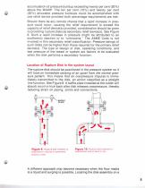
accumulation of pressure buildup exceeding twenty percent (20%) above the MAWP. The ten per cent (10%) and twenty per cent (20%) alfowable pressure buildups could be accomplished with one relief device provided both percentage requirements are met. Should there be any remote chance that a rapid increase in pres- sure could occur, causing the relief requirement to exceed the capacity of relief device(s) provided, consideration should be given to providing rupture disks as secondary relief device(s). See Figure 8. Such a rapid increase in pressure might be attributed to an exothermic reaction or...
Open the catalog to page 6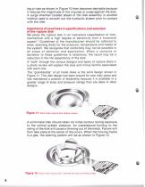
leg or riser as shown in Figure 10 then becomes desirable because it reduces the magnitude of the impulse or surge against the disk. A surge chamber located ahead of the disk assembly is another method used to smooth out the hydraulic stream prior to contact Importance of exactness in specifications and selection We place the rupture disk in an instrument classification of l,non- mechanical with a high degree of sensitivity from a functional aspect." Guidelines of the manufacturer should be adhered to when selecting disks for the pressure, temperature and media of the system. We recognize that...
Open the catalog to page 7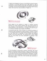
If media to be released is a liquid in a completely hydraulic system, a reduction in the relief area may occur. See Figure 13. This is attributed to the fast pressure drop after the capacity requirement is satisfied. Volume to be discharged may cause the disk to have a larger relief area than the one shown in Figure 13. Facts related to the tolerance or margin in pressure required between the normal system pressure and disk rating cannot be fully explored in this discussion. A more complete review of all disks presented in this discussion is included in the specific prod- uct literature available...
Open the catalog to page 8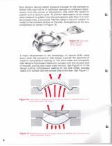
Disk designs having system pressure imposed on the concave or dished side may not be of sufficient strength to withstand defor- mation from the convex or atmospheric side when the vessel or system is on a vacuum cycle. To prohibit deformation of the metal when pressure is greater from the atmospheric side than it is from the process side, a structural member called a vacuum support is mated to the concave contour of the disk. Arrangement of the two components is shown in Figure 15. A major advancement in the technology of rupture disks came about when the concept of disk design involved the exposure...
Open the catalog to page 9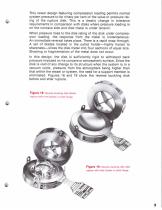
This newer design featuring compression loading permits normal system pressure to be ninety percent of the value or pressure rat- ing of the rupture disk. This is a drastic change in tolerance requirements in comparison with disks where pressure loading is on the concave side and disk metal is under tension. When pressure rises to the disk rating of the disk under compres- sion loading, the response from the metal is instantaneous. An immediate reversal takes place. There is a rapid snap through. A set of blades located in the outlet holder—highly honed to sharpness—slices the disk metal into...
Open the catalog to page 10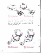
Figure 20: Scored type reverse buckling rupture bisk before ruplure Figure 21: Scored typo reverse buckling rupture disk, alter ruulure Further research on disks under compression involves the design shown in Figures 20 and 21. Scoring the metal eliminates the need for knife blades. From the functional aspect, this disk duplicates the design where the blade structure is used to cut and open the disk. Figures 22 and 23 show the complete assembly with unruptured and ruptured disk. Figure 22: Complete rupture disk assembly with scored reverse buckling ruplure disk, before ruplure. Figure 23: Complete...
Open the catalog to page 11All BS&B SAFETY SYSTEMS, L.L.C. catalogs and technical brochures
 GLP-S™ Reverse Buckling Disk
2 Pages
 LO-TO-FLO™ Safety Head
2 Pages
 VENT-SAF™ Explosion Panels
4 Pages
 Buckling Pin Relief Technology
12 Pages
 Burst Disk Monitors™ (BDM)
4 Pages
 Burst Alert® Sensor
4 Pages
 VIS-U-TEC™ Sensor
2 Pages
 Type D
8 Pages
 Tank Car Rupture Disks
2 Pages
 Rupture Disk
12 Pages
 Corporate Profile
20 Pages
 The VAC-SAF? System
12 Pages
 SAF-T-GRAF? Graphite Disks
4 Pages
 SURE-SAF? System
4 Pages
 ECO-SAF? System
8 Pages
 GCR-S? Reverse Buckling Disk
2 Pages
 BIO-SAF? System
16 Pages
 GLP-S? Reverse Buckling Disk
2 Pages
 SmartSystem
4 Pages
 MRB series
1 Page
 SIGMA, SIGMA EXL
4 Pages
 VENT-SAF? Explosion Vents
8 Pages
 EXPLOSION VENTING
4 Pages
 AVB
AVB2 Pages
 Nu-Saf Plus
8 Pages
 Type B
8 Pages
 Conversion Factors
2 Pages
 SR-TC Rupture Disk
2 Pages
 Composite Bursting Disc Type D
12 Pages
 SKR-U Reverse Buckling Disk
4 Pages
 The STA-SAF System
12 Pages
 Mono Block Graphite Disks
8 Pages


