PRISMIC R10

PRISMIC R10
The PRISMIC R10 is an electronic unit designed to detect rotor earth faults in brushless generators. It allows for early detection of a single earth fault, enabling planned maintenance and preventing further damage from a second fault.
Description
The PRISMIC R10 uses an electronic unit to monitor rotor winding conditions without the need for brushes and sliprings, enhancing reliability and reducing maintenance costs. It consists of a transmitter connected to the rotor winding and a stationary receiver.
Transmitter
The transmitter connects to the rotor and generates an isolated DC source for fault detection. In normal conditions, it emits a high-frequency signal. An earth fault causes current flow, stopping the signal and triggering a fault condition.
Receiver
The receiver detects the transmitted signal, filtering out noise and preventing false alarms. It energizes an alarm relay upon detecting a fault, with a time delay to avoid nuisance alarms. It includes circuits to inhibit relay energization during low voltage conditions.
Technical Details
- Earth Fault Detection Sensitivity: Sensitivity varies with fault position and rotor voltage, with least sensitivity at 12kΩ on the negative side and up to 157kΩ on the positive side.
- Fault Sensing Current: Approximately 1.5mA.
- Time Delay on Operation: 1 second.
Specifications
- Transmitter Centrifugal Force Limit: Suitable for mounting at a radius of up to 115mm at 3,600 rev/min, with overspeed capability of 4,800 rev/min for 5 minutes.
- Transmitter Weight: 710g ±25g.
- Output Relay Rating: 200VA or 100W, maximum 5A or 250V.
- Temperature Range: Receiver: -25°C to +85°C; Aerial and Transmitter: -25°C to +70°C (operating), -40°C to +100°C (storage).
- Receiver Auxiliary Supply: 110V, 220V, 264V, or 400V, ±25%, 50Hz to 500Hz.
- Transmitter Supply (Rotor Voltage): Maximum continuous voltage: 200V dc; Overload voltage: 500V dc; Minimum operating voltage: 30V dc.
Additional Features
- Loss of Auxiliary Supply: Relay inhibited below 75% of nominal transformer tap rating.
- Low Exciter Field Voltage Inhibit: Adjustable from 3V to 25V, with a time delay of 3 to 4 seconds for inhibit release.
- Distance Limitation: Limited by cable capacitance and resistance.
- Test Facility: External test button simulates an earth fault for alarm testing.
- Indication of Circuit Conditions: LEDs indicate various operational states.
Catalog excerpts

PRISMIC® R10 Rotor Earth Fault Monitor PRODUCT SPECIFICATION Introduction The PRISMIC R10 is an electronic unit designed to provide a brushless generator with an alarm in the event of a rotor earth fault. General practice on generators with brushless excitation is for the rotor (main field) winding to be fully isolated from earth so that, in the event of a single earth fault, the generator could continue running. However, a second earth fault would short circuit part of the winding, necessitating an immediate shutdown and corrective action. Detection of a single earth fault allows the generator to be taken out of service for investigation and repair at the earliest opportunity, usually as part of a planned maintenance programme. Fig.1 Transmitter fitted to generator rotor To continuously monitor the condition of the rotor winding, the BRUSH PRISMIC R10 rotor earth fault monitor (REFM) uses an electronic unit to detect a single earth fault. This dispenses with the need for brushes and sliprings, resulting in enhanced reliability and reduced maintenance costs. The detector comprises a rotating transmitter, connected to the rotor winding, which transmits an infra red signal to a stationary receiver. Transmitter The transmitter has three electrical connections to the rotor; to earth, rotor positive and rotor negative. The rotor voltage provides the power supply for the unit, from which it generates its own isolated dc source, which is used as the earth fault detection supply. The negative of this isolated source is tied to ground, the positive to the rotor negative. During healthy conditions, the current flowing from the isolated dc source is negligible and the transmitter produces a high frequency signal that is detected by the receiver aerial and the receiver indicates no fault. Any earth fault on the rotating assembly, either on the armature or the rotor winding, will cause a current to flow from the dc source. This current is detected and used to remove the transmitted high frequency signal. By removing the signal the detection system becomes “fail-to-safe”, in that a loss of transmitted signal is detected as an earth fault condition. Fig.2 Receiver in IP66 enclosure for generator mounting Receiver The transmitted signal is sensed by an aerial and fed, via screened cable and amplifier, into a “phase locked loop” within the receiver. This device locks on to the transmitted signal and serves to decode the pulse signal as well as filter out any background noise caused by external sources. The decoded signal is used to hold off the output alarm relay after an amplification and time delay stage. In the event of an earth fault condition the alarm relay becomes energised after a short time delay (incorporated to suppress “nuisance” alarms) thereby giving external indication of the fault condition. Fig.3 Receiver mounted in IP20 enclosure for generator control panel mounting The power supply required by the receiver is normally provided by the excitation controller power source (usually a permanent magnet generator). During run up on excitation controller over flux control, or during normal off load transients, the available rotor voltage may be too low to ensure correct transmitter operation. To overcome this, a circuit is incorporated in the receiver to inhibit output relay energisation on either low exciter field voltage or low auxiliary ac supply voltage. A time delay stage within this circuit allows the rotor voltage to build up prior to giving a permissive output.
Open the catalog to page 1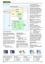
Technical details Loss of Auxiliary Supply The output relay will be inhibited when the supply falls below 75% of the nominal transformer tap rating. If the exciter field voltage falls below the preset level, the inhibit will be applied instantaneously. The maximum continuous exciter field voltage at this input is 400V dc. Distance between IR Detector and Receiver This is limited by the interconnecting screened cable to a maximum of 0.1µF per core to screen and the resistance not exceeding 10Ω per core. R10 REFM Receiver Detector Loss of Excitation Detector Test switch Loss of power supply detector...
Open the catalog to page 2All Brush HMA catalogs and technical brochures
 Transformers
1 Page
 Tapchangers
2 Pages
 PRISMIC A12
2 Pages
 MAVR upgrade
4 Pages
 PRISMIC A30
2 Pages
 PRISMIC T20
2 Pages
 PRISMIC A32
2 Pages
 PRISMIC A50
4 Pages
 PRISMIC PMS upgrade
5 Pages
 PRISMIC PMS
11 Pages
 hydrogen dryer
2 Pages
 DG 4 Pole Turbogenerators
4 Pages
 AC Traction
2 Pages
 Hydrogen Cooled Generators
2 Pages
 DAX 2 Pole Turbogenerators
4 Pages

Archived catalogs
 4 pole Turbogenerators
4 Pages