
- Catalogs
- Brugg Pipesystems
- Premant Catalogue


- Company
- Products
- Catalogs
- News & Trends
- Exhibitions
Premant Catalogue

Premant Catalogue
PREMANT is a pre-insulated steel pipe system designed for transporting district heat directly in the ground without channels. It is suitable for heating water, domestic hot water, water/glycol mixtures, and condensates, but not steam. The system uses rigid polyurethane foam insulation and a PE-HD casing pipe for protection. It is modular, with prefabricated units and preformed parts, facilitating easy planning and installation. Components are connected on-site with circumferential seams, and joints provide supplementary insulation.
- Maximum continuous operation temperature: 144°C (160°C)
- Maximum operating pressure: 25 bar
- Medium pipe materials: Steel (welded, seamless, galvanized, or stainless steel)
- Insulation: Rigid polyurethane foam
- Casing pipe: PE-HD
- Standards: EN 253, 448, 488, 489
- Medium pipes: Steel pipes with longitudinal or helical seam welds
- Preformed parts: T-pieces, bends, and fittings
- Monitoring wires: For moisture identification
- Thermal insulation: Polyurethane foam
- Casing pipe: PE-HD
Pressure drop and heat loss calculations are essential. Pipe routing and maximum installed length considerations are crucial. Installation can be done with or without thermal pre-stressing. Expansion components and guidelines are provided.
Guidelines for underground construction and installation are detailed. Proper storage and transport of preformed parts are necessary. Tapping technology and sectional drainage/venting are described.
Heat loss calculations are provided for different insulation thicknesses and installation types. U-values and heat transfer coefficients are specified for various pipe sizes and temperatures.
The PREMANT district heating pipe system is a robust and reliable solution for district heating applications, offering flexibility in design and installation while adhering to industry standards.
Heat loss during operation is calculated using the formula q = U · (TB - TE) [W/m]. Tables provide U-values and corresponding heat losses for various average temperatures ranging from 50°C to 130°C.
Type of installation is a 2-pipe system laid in the ground with a pipe distance of 0.20 m and a coverage height of 0.8 m. Soil conductivity is 1.2 W/mK, PE jacket conductivity is 0.4 W/mK, and PUR foam conductivity is 0.0260 W/mK. Guidelines for pipe routing emphasize the use of L-bends, Z-bends, and U-bends to accommodate thermal expansion.
Pipe routing should consider expansion capability, with right-angled routing preferred. Minimum bending radius is specified for different pipe diameters. Elbow pipes are pre-insulated and designed to optimize routing changes.
When positioning branches, the movement of connecting pipes is impeded by the surrounding ground, forming natural fixed points. Different movements and force ratios between main and connection pipes must be considered.
Details on nominal widths, outer diameters, insulation thicknesses, and delivery lengths are provided for various pipe sizes. Elbow pipes are manufactured to customer specifications with straight ends due to production constraints.
Installation instructions emphasize proper welding and protection against overheating. The document advises on the use of expansion pads and ensuring freedom of movement for certain components.
The components conform to EN448 and EN10253 standards. Reduction pieces are designed to reduce dimensions by a maximum of two steps for static reasons.
Use processed, demineralized, clean tap water with low oxygen content. Avoid installation in areas with bends and expansion limbs. Systematic heat insulation for ball valves is important.
Tables with detailed measurements for various components, such as reduction pieces and vents, along with their weights. Materials used include steel and stainless steel, and types of seals and insulation are specified.
Initial switching should occur only after flushing the pipe. In frost conditions, ensure uncovered fittings are emptied completely. Grease steel parts on the dome thoroughly. If a provisional pipe end exists, weld it shut.
Use milled-in notch on switch spindle square and pointer for position indication. Close by turning clockwise to the stop (90° for ball valve).
Use matching socket wrenches for switching. Plug-on gears are recommended for DN 200 and above. Avoid applying force to the switching shaft and do not overtighten end stops. Intermediate positions are not allowed for ball valves to prevent wear on seals.
Regularly clean and grease steel parts on the dome. Switch between OPEN and CLOSED positions several times every 3 months. Check the freedom of movement of the dome and groundwater level and condition.
Adherence to instructions is essential. No warranty for damage due to incorrect installation, handling, or maintenance.
Nominal widths and corresponding dimensions for ball valves are provided, including steel pipe diameter, insulation thickness, standard length, and wrench size.
Non-cross-linked and cross-linked PE shrink sleeves are used for watertight connections, with technical requirements as per EN 489 and AGFW Worksheet FW401. Shrink-on reduction sleeves are designed for steel reduction joints, reducing dimensions by a maximum of three steps.
Brugg VISUCON allows visual inspection of polyurethane foam without destroying the sleeve. EWELCON electro-welding joint provides watertight and gastight connections for plastic pipes, suitable for repairs and refurbishments.
The document provides detailed specifications for the EWELCON-S Electro-Welding Joint, designed for smaller dimension ranges. The joint consists of a shrink-on sleeve made from bimodal PE-HD and heating elements with a temperature sensor.
The EWELCON-S system includes a shrink-on sleeve and prefabricated heating elements. The sleeve is fitted with solar protection foil and is pushed onto the casing pipe before welding. The system ensures high-quality joints even in difficult installation locations.
The installation process emphasizes cleaning and drying the weld seam area. The shrink sleeve is shrunk onto the casing pipe ends using a propane gas flame. The welding process parameters are stored for documentation, and each joint undergoes visual inspection and a tightness test.
Tables with dimensions for casing pipes, heating elements, and fitting bends are included. Materials used include PE80 and HDPE, with details on the shrink-on closure material.
Guidelines for transporting and storing pipes and preformed parts are provided. Pipes should be stored in a dry, covered location on planks or wooden pallets.
Safety and environmental guidelines for storing and disposing of foam components are included. Compliance with environmental protection standards and local waste disposal laws is emphasized.
Classification of substances used in the PREMANT district heating pipe system is outlined. Storage conditions require a temperature range of 10 to 25°C, with ventilation twice every 24 hours.
The installation involves several critical steps to ensure proper function and safety. The outer PE casing must remain undamaged, and PE sleeve pipes should be positioned correctly before welding.
General construction regulations must be followed when excavating pipe trenches. The trench must remain clear of water, and pipes should be installed on foam pipe supports or sandbags.
The trench profile should adhere to DIN 4124 standards, with specific dimensions for trench widening in the area of expansion pads.
The pipe trenches should be filled with compactable washed sand. Residual infill should use compactable materials like excavated material or fine gravel.
Specifications for concrete block dimensions to handle maximum fixed point forces are provided. The foundation dimensions are based on a frictional angle of 32.5° for friable soils.
Tapping systems are designed for creating pipe branches under pressure. The tapping device can be used for branch dimensions of DN 25 to DN 100.
The preparation of weld seams and seam structures is detailed, emphasizing the importance of cooling the fitting between weld seam layers.
Catalog excerpts
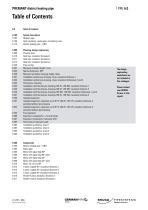
PREMANT district heating pipe 6.106 Heat insulation, casing pipe, monitoring wires 6.115 District heating pipe - UNO 6.200 Planning, design engineering The design engineering worksheets are not included in this catalogue. Please contact your BRUGG Partner in this regard. 6.231 Maximum installed length, Lmax 6.232 Natural fixed point, NFP 6.240 Maximum permitted coverage height, Hmax 6.241 Installation without pre-stressing, Lmax, insulation thickness 1 6.242 Installation without pre-stressing, Lmax, insulation thicknesses 2 and 3 6.246 Installation with thermal pre-stressing, DN 350 - DN 500, insulation thicknesses 1 and 2 6.251 Impeded expansion; expansion up to 90 °C, DN 20 - DN 125, insulation thickness 2, permitted without pre-stressing 6.252 Impeded expansion; expansion up to 90 °C, DN 20 - DN 125, insulation thickness 3, permitted without pre-stressing 6.260 Expansion components; L, Z and U bends 6.261 Expansion components, transverse shift 6.262 Positioning of expansion pads 8.1.2015 BRG Subject to technical changes GERMANPIPE G BRUGG PIPESYSTEMS Flexible solutions
Open the catalog to page 1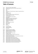
PREMANT district heating pipe 6.318 Parallel T-piece; heating, insulation thickness 3 6.320 Fixed point; thermally and electrically separated, insulation thickness 2 6.325 Fittings installed in the ground; description, installation and operating instructions 6.330 Ball valve 6.332 Ball valve with 2 vents 6.333 Ball valve with 1 vent 6.334 Ball valve for installation in the ground, installation diagram 6.335 Accessories: shut-off fitting, ball valve 6.340 Joint; shrink sleeves 6.342 Joint, shrink-on reduction sleeve/end sleeve 6.350 EWELCON electro-welding joint, system...
Open the catalog to page 2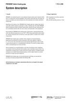
PREMANT district heating pipe System description 1. General PREMANT is the protected name for a pre-insulated steel pipe system used to transport district heat. It is a pipe system for direct installation in the ground, without channels. The system has proven its excellence over several decades and is now recognized as the industry standard for normal cases. Max. temperature for continuous operation TBmax: 144 °C (160 °C) Max. permitted operating pressure p: 25 bar Depending on the purpose of use, PREMANT district heating pipe has a medium pipe made of steel, either welded, seamless or galvanized,...
Open the catalog to page 3
PREMANT district heating pipe System 1. Medium pipe Bars: description steel pipes with longitudinal or helical seam welds Quality: 0 < 323.9 mm P235TR1 or P235GH as per; EN 10220/EN 10217-1 Test certificate: EN 10204 - 3.1 Welding bevel: Wall thickness > 3.2 mm acc. to DIN 2559-1 Index 21 and 22 Preformed parts: T-pieces are flared, from longitudinal seam-welded steel pipes, or made of welded t-pieces acc. to EN 10253; material is the same as for straight welded pipes. Quality: P235TR1 or P235GH as per; EN 10220/EN 10217 Test certificate: EN 10204 - 3.1 Welding bevel: Wall thickness...
Open the catalog to page 4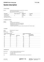
PREMANT district heating pipe 2. Thermal insulation Material: Polyurethane foam (pentane-blown), manufactured from 3 components: polyol, isocyanate and cyclopentane High-pressure plants are used for mixing and metering. PUR insulation Reference temperature °C PREMANT value Test standard Compression strength - > 0.3 MPa EN 253 Thermal conductivity 50 < 0.0260 W/mK DIN 52612 Percentage of closed cells - > 96 % Water absorption after 24 hours - < 10 % 2.1 Supplementary insulation Standard: EN 489 Execution: - Executed by trained installation staff...
Open the catalog to page 5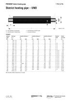
PREMANT district heating pipe D = outer diameter of casing pipe s = wall thickness of medium pipe d = outer diameter of medium pipe t = insulation thickness PREMANT Nominal Steel pipe Insulation thickness 1 Insulation thickness 2 Insulation thickness 3 Standard Volume width d x s D D D length Inner pipe We will deliver different dimensions on request. Subject to technical changes GERMANPIPE G BRUGG PIPESYSTEMS Flexible solutions
Open the catalog to page 6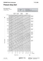
PREMANT district heating pipe Pressure drop chart Water temperature 80 °C Surface roughness e = 0.045 mm (1 mmWS = 9.81 Pa) Flow rate in kg/h Power requirement in kW Temperature difference, VL(flow)/RL(return) in °C
Open the catalog to page 7
PREMANT district heating pipe Heat loss Insulation thickness 1 a TE H 1e \pe ^PUR Type of installation: Pipe distance: Ground temperature: Coverage height: Soil conductivity: Conductivity of PE jacket: Conductivity of PUR foam: Heat losses q [W/m] for one pipe Heat loss during operation: q = U ■ (Tb - Te) [W/m] U = Heat transfer coefficient [W/mK] Tb = Average temperature between VL/RL [°C] Te = Average ground temperature [°C] Subject to technical changes GERMAN 1PI G BRUGG PIPESYSTEMS Flexible solutions
Open the catalog to page 8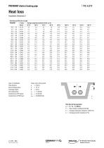
PREMANT district heating pipe Heat loss Insulation thickness 2 a TE H 1e \pe ^PUR Type of installation: Pipe distance: Ground temperature: Coverage height: Soil conductivity: Conductivity of PE jacket: Conductivity of PUR foam: Heat losses q [W/m] for one pipe Heat loss during operation: q = U ■ (Tb - Te) [W/m] U = Heat transfer coefficient [W/mK] Tb = Average temperature between VL/RL [°C] Te = Average ground temperature [°C] Subject to technical changes GERMAN 1PI G BRUGG PIPESYSTEMS Flexible solutions
Open the catalog to page 9
PREMANT district heating pipe Heat loss Insulation thickness 3 a TE H 1e \pe ^PUR Type of installation: Pipe distance: Ground temperature: Coverage height: Soil conductivity: Conductivity of PE jacket: Conductivity of PUR foam: Heat losses q [W/m] for one pipe Heat loss during operation: q = U ■ (Tb - Te) [W/m] U = Heat transfer coefficient [W/mK] Tb = Average temperature between VL/RL [°C] Te = Average ground temperature [°C] Subject to technical changes GERMAN 1PI G BRUGG PIPESYSTEMS Flexible solutions
Open the catalog to page 10
PREMANT district heating pipe Pipe routing for PREMANT district heating pipe is not subject to any special requirements. In relation to the pipe, it should mainly be selected on the basis of expansion capability. In normal pipe routing, changes of direction using L-bends are the first choice for this purpose. Then come Z-bends and U-bends, which accommodate the expansion that occurs at precisely defined points. The angular dimensions of the 'expansion bend' should not exceed 90°, otherwise substantially longer expansion limbs are needed; whenever possible, right-angled pipe routing should be...
Open the catalog to page 11All Brugg Pipesystems catalogs and technical brochures
 BRUGG-STAMANT Safety Pipe
14 Pages
 Spiramant Flyer
2 Pages
 Brugg Seminars
20 Pages
 Flexwell-LPG Piping
2 Pages
 Flexwell Safety pipe technology
32 Pages
 Biogas technology Flyer
24 Pages
 LMS 320 Monitoring device
2 Pages
 LMS 120 Monitoring device
2 Pages
 AdBlue Flyer
2 Pages
 Eigerflex Catalogue
25 Pages
 Casaflex catalogue
32 Pages
 Flexwell Catalogue
33 Pages
 Urbanflex
2 Pages
 CALPEX Leaflet
8 Pages
 CALPEX district heating pipe
56 Pages
 CALPEX PUR-KING
6 Pages
 COOLMANT
22 Pages
 COOLFLEX
27 Pages
 Datasheet Secon-X
2 Pages
 NIROFLEX Flyer
6 Pages
 Leak Monitoring Systems
8 Pages
 FLEXWELL-LNG Small Scale
4 Pages
 BRUGG-STAMANT Safety Pipe
2 Pages
 FLEXWELL-LPG
16 Pages
 SECON-X Brochure
20 Pages
 Hotelflyer
6 Pages
 Cooling Flyer
4 Pages
 Biogastechnik Flyer
13 Pages
 COOLMANT/COOLFLEX Flyer
8 Pages
 FSR Flyer
6 Pages
 SPIRAFLEX Brochure
6 Pages
 FLEXWELL FHK
6 Pages
 PREMANT Brochure
6 Pages
 CASAFLEX brochure
8 Pages
 FSR Brochure
32 Pages
 Datasheet PETREX
2 Pages
 EIGERFLEX Flyer
4 Pages
 CRYOFLEX
6 Pages


