
Catalog excerpts

2.100 System description (general) 2.105 System description (data) 2.115 COOLFLEX range, DN 20 - DN 125/ SDR 11 (coils) 2.2 Planning, design engineering 2.200 Pressure loss chart for water, DN 20 - DN 125/SDR 11 2.201 Pressure loss chart for ethylene glycol, DN 20 - DN 125 / SDR 11 2.300 House entry bend, 90° 2.315 COOLFLEX L-shell, dimension 0 76 - 126 mm 2.316 COOLFLEX Big L-shell, dimension 0 162 - 182 mm 2.320 Joint (PE-HD shrink sleeve), dimension 0 76 - 182 mm 2.325 COOLFLEX l-shell, dimension 0 76 - 126 mm 2.326 COOLFLEX Big l-shell, dimension 0 162 - 182 mm 2.330 COOLFLEX T-shell, dimension 0 76 - 126 mm 2.335 COOLFLEX Big T-shell, dimension 0 162 - 182 mm 2.350 PE jointing methods, screwed connectors (external thread, weld end, coupling) 2.355 PE jointing methods, screwed connectors, T-pieces 2.359 PE jointing methods, fusion welded 2.360 PE jointing methods, alternative connections 2.365 End closure, shrink-type closure, end cap (LD-PE) 2.370 Wall sealing ring for wall openings 2.375 Building entry, wall opening 2.380 Building entry, core bores/cement pipe liners 2.5 Underground construction, installation Subject to technical modifications. BRUGG/ PIPESYSTEMS
Open the catalog to page 1
System description 1. General COOLFLEX is the registered trade name for a flexible pipe system from Brugg Pipe Systems. This pipe system is especially suitable for use in local and district cooling networks, in industrial and with restrictions also for combined heat pump systems (cooling and heating). Max. continuous operating temperature TBmax: –20 to +40 °C* Max. permitted operating pressure p: max. 16 bar The COOLFLEX district cooling pipe has a carrier pipe produced from high-density polyethylene (PE100) as per standard EN 12162. The polyethylene pressure pipes are the standard for...
Open the catalog to page 2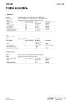
System description Life expectancy: Polyethylene class PE100 with high density, to DIN EN ISO 12162 suitable as district cooling, cold water and waste water pipe Reference temperature Value Test standard Thermal conductivity Tensile strengts Linear expansion coefficient Crystallite melting range CFC-free, 100 % C02-blown polyurethane foam (PUR) Reference temperature Flexible pipes Test standard Thermal conductivity Percentage of closed cells Water absorption after 24 hours Material: linear polyethylene, low density (LLD-PE), seamlessly extruded Purpose: mechanical protection and moisture...
Open the catalog to page 3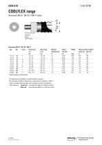
COOLFLEX range Outer casing Minimum Volume Weight Dxs1 Bending radius Inner pipe Maximum delivery lengths* Jumbo coil Maxi coil Partial lengths can be delivered - All dimensions are available in straight lengths on request. - We will produce different dimensions or special items on request (> 500 m). - Larger or smaller delivery lengths can be supplied on drums if requested. - Coil dimensions: Jumbo coil outer diameter 2800 mm x 800 mm (width) Maxi coil outer diameter 2800 mm x 1200 mm (width) Subject to technical modifications. BRUGG/ PIPESYSTEMS
Open the catalog to page 4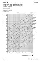
Pressure loss chart for water DN 20 - DN 125 / SDR 11 Water temperature 10 °C Roughness = 0.01 mm (PE100) (1 mmWS = 9.81 Pa) Velocity 8.1.2015 Subject to technical modifications.
Open the catalog to page 5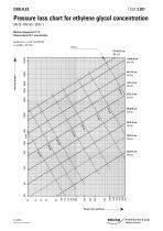
Pressure loss chart for ethylene glycol concentration DN 20 - DN 125 / SDR 11 Medium temperature 10 °C Ethylene glycol 30 % concentration Roughness = 0.01 mm (PE100) (1 mmWS = 9.81 Pa) 8.1.2015 Subject to technical modifications.
Open the catalog to page 6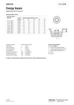
Energy losses Applications laid in the ground Installation type CLX: Pipe distance: Covera above pipe: Ground temperature: Soil conductivity: Conductivity of PUR foam: Conductivity of PE pipe: Conductivity of PE casing: On request, we shall be glad to calculate the heat losses for surface mounted pipe systems. 8.1.2015 Subject to technical modifications. Heat loss during operation: q = U (TB -TE) [W/m] U = Heat transfer coefficient [W/mK] TB = Average operating temperature [°C] TE = Average gr
Open the catalog to page 7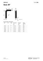
Type DN Inches PE inner pipe Outer pipe Volume Subject to technical modifications. BRUGG/ PIPESYSTEMS
Open the catalog to page 8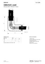
COOLFLEX L-shell COOLFLEX L-shell 2 PE fusion welded joints; see CLX 2.359 6 Reducer ring or sealing ring Subject to technical modifications. BRUGG/ PIPESYSTEMS
Open the catalog to page 9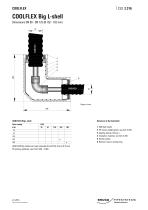
COOLFLEX Big L-shell Dimensions DN 80 - DN 125 (Ø 162 - 182 mm) 1 ABS half-shells 2 PE fusion welded joints; see CLX 2.359 3 Sealing clamps (24 pcs.) 4 Insulation material; see CLX 2.345 5 Glued surface 6 Reducer ring or sealing ring COOLFLEX Big-shells are freely reducible from Ø 182 mm to Ø 76 mm PE jointing methods; see CLX 2.350 - 2.360 8.1.2015 Subject to technical modification
Open the catalog to page 10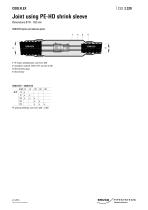
Joint using PE-HD shrink sleeve Dimensions Ø 76 - 182 mm COOLFLEX joints and reduction joints 1 PE fusion welded joints; see CLX 2.359 2 Insulation material, PUR or PE; see CLX 2.345 3 Shrink sleeve pipe 4 Shrink hose COOLFLEX – COOLFLEX Ø d2 76 91 126 162 182 Ø d1 76 x 91 x x 126 x x x 162 x x 182 x x x PE jointing methods; see CLX 2.350 - 2.360 8.1.2015 Subject to technical modifications.
Open the catalog to page 11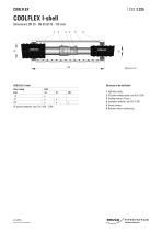
COOLFLEX I-shell Dimensions DN 20 - DN 65 (Ø 76 - 126 mm) 2 COOLFLEX I-shell Subject to technical modifications. 1 ABS half-shells 2 PE jusion welded joints; see CLX 2.359 3 Sealing clamps (12 pcs.) 4 Insulation material; see CLX 2.345 5 Glued surface 6 Reducer ring or sealing ring
Open the catalog to page 12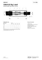
COOLFLEX Big I-shell Dimensions DN 80 - DN 125 (Ø 162 - 182 mm) 4 1 ABS half-shells 2 PE jusion welded joints; see CLX 2.359 3 Sealing clamps (22 pcs.) 4 Insulation material; see CLX 2.345 5 Glued surface 6 Reducer ring or sealing ring COOLFLEX Big-shells are freely reducible from Ø 182 mm to Ø 76 mm PE jointing methods; see CLX 2.350 - 2.360 8.1.2015 Subject to technical modification
Open the catalog to page 13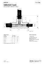
COOLFLEX T-shell Dimensions DN 20 - DN 65 (Ø 76 - 126 mm) Structure of the half-shell Branch, Ø d2 76 91 x x x x x x x x x x x x 8.1.2015 Subject to technical modifications. 1 ABS half-shells 2 PE T-piece; see CLX 2.359 3 Sealing clamps (16 pcs.) 4 Insulation material; see CLX 2.345 5 Glued surface 6 Reducer ring or sealing rin
Open the catalog to page 14All Brugg Pipesystems catalogs and technical brochures
-
BRUGG-STAMANT Safety Pipe
14 Pages
-
Spiramant Flyer
2 Pages
-
Brugg Seminars
20 Pages
-
Flexwell-LPG Piping
2 Pages
-
Flexwell Safety pipe technology
32 Pages
-
Biogas technology Flyer
24 Pages
-
LMS 320 Monitoring device
2 Pages
-
LMS 120 Monitoring device
2 Pages
-
AdBlue Flyer
2 Pages
-
Eigerflex Catalogue
25 Pages
-
Premant Catalogue
70 Pages
-
Casaflex catalogue
32 Pages
-
Flexwell Catalogue
33 Pages
-
Urbanflex
2 Pages
-
CALPEX Leaflet
8 Pages
-
CALPEX district heating pipe
56 Pages
-
CALPEX PUR-KING
6 Pages
-
COOLMANT
22 Pages
-
Datasheet Secon-X
2 Pages
-
NIROFLEX Flyer
6 Pages
-
Leak Monitoring Systems
8 Pages
-
FLEXWELL-LNG Small Scale
4 Pages
-
BRUGG-STAMANT Safety Pipe
2 Pages
-
SECON-X Brochure
20 Pages
-
FLEXWELL-LPG
16 Pages
-
Hotelflyer
6 Pages
-
Cooling Flyer
4 Pages
-
Biogastechnik Flyer
13 Pages
-
FSR Flyer
6 Pages
-
PREMANT Brochure
6 Pages
-
CASAFLEX brochure
8 Pages
-
FLEXWELL FHK
6 Pages
-
COOLMANT/COOLFLEX Flyer
8 Pages
-
FSR Brochure
32 Pages
-
SPIRAFLEX Brochure
6 Pages
-
Datasheet PETREX
2 Pages
-
EIGERFLEX Flyer
4 Pages
-
CRYOFLEX
6 Pages


